R CASTILE PELLET INSERT Owner’s Manual Tested and Listed by Installation and Operation Portland Oregon USA O-T L C US OMNI-Test Laboratories, Inc. Models: 810-02901 (MBK) 810-03201 (PMH) CASTINS-CSB CASTINS-CWL CAUTION DO NOT DISCARD THIS MANUAL • Important operating and • Read, understand and maintenance instrucfollow these instructions included. tions for safe installation and operation. WARNING • Leave this manual with party responsible for use and operation.
R Castile Pellet Insert Hearth & Home Technologies welcomes you to our tradition of excellence! In choosing a Quadra-Fire appliance, you have our assurance of commitment to quality, durability, and performance. SAMPLE OF CLEARANCE TO COMBUSTIBLES LABEL LOCATION: On beaded chain behind right access panel. Panel hinges open. This commitment begins with our research of the market, including ‘Voice of the Customer’ contacts, ensuring we make products that will satisfy your needs.
R Castile Pellet Insert TABLE OF CONTENTS Section 1: Listing and Code Approvals A. B. C. D. E. Section 8: Operating Instructions Appliance Certifications ......................4 Mobile Home Approved ......................4 Glass Specifications ............................4 Electrical Rating ..................................4 BTU & Efficiency Specifications ..........4 A. B. C. D. E. F. G. H. Section 2: Getting Started A. Design, Installation & Location Considerations ....................................
R Castile Pellet Insert 1 Listing and Code Approvals E. BTU & Efficiency Specifications A. Appliance Certification MODEL: Castile Pellet Insert LABORATORY: OMNI Test Laboratories, Inc Particulate Emissions Rating: .7 grams/hr REPORT NO. 061-S-42-2 *BTU Output: 8,000 - 30,000 / hr TYPE: Solid Fuel Room Heater/Pellet Fuel Burning Type Insert Heating Capacity: up to 1,500 sq. ft.
R Castile Pellet Insert 2 Getting Started A. Design, Installation & Location Considerations B. Fire Safety 1. Appliance Location Consideration must be given to safety, convenience, traffic flow, and the fact that the appliance will need a chimney and chimney connector. It is a good idea to plan your installation on paper, using exact measurements for clearances and floor protection, before actually beginning the installation.
R Castile Pellet Insert D. Inspect Appliance & Components and Pre-Use Check List C. Tools And Supplies Needed Tools and building supplies normally required for installation, unless installing into an existing masonry fireplace: Reciprocating Saw Hammer Phillips Screwdriver Tape Measure Plumb Line Level Framing Material Hi-temp Caulking Material Gloves Safety Glasses Framing Square Electric Drill & Bits (1/4”) 1/4” Self-Tapping Screws 1.
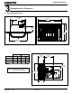
R Castile Pellet Insert 3 Dimensions and Clearances A. Appliance Dimensions 28-1/16" 43-1/2" (713mm) (1105mm) 23-7/16" 42-1/2" (1080mm) 8" (595mm) (203mm) 11-1/16" (281mm) 30-3/8" (772mm) 30" (762mm) 32-5/16" (821mm) Figure 7.1 - Top View Figure 7.
R Castile Pellet Insert B. Clearance To Combustibles, UL and ULC AS A BUILT-IN A C D B B C E 0” (0mm) Clearance To Exposed Section And Face Trim Figure 8.1 Inches Millimeters A Top of Hopper Top or Rear Vent 0 0 B Side of Outside Skin Top or Rear Vent 0 0 C Back of Hopper Top Vent 2.5 64 Rear Vent 0 0 D Vent Pipe to Combustible Top or Rear Vent 3.0 76 E Front Panel Edge Top or Rear Vent 0 0 INSTALLED AS A BUILT-IN UNIT Shown Optional Outside Air WARNING Fire Risk.
R Castile Pellet Insert C. Masonry and Zero Clearance Fireplaces Inches Millimeters MANTEL SIDE WALL B C A Insert side to combustible side wall 0 0 B Insert top to mantel 12 305 C Insert top to face trim 0 0 D Insert side to face trim 0 0 D A E F Figure 9.1 D. Floor Protection Inches Millimeters E Floor protection hearth extension from door opening 6 152 F Floor protection to the side of door opening 6 152 E.
R Castile Pellet Insert F. Removing Metal Floor of Factory-Built Firebox • • • The firebrick (refractory), glass doors, screen rails, screen mesh and log grates can be removed from a factory-built firebox in order to gain minimum insert opening requirements. Any smoke shelves, shields and baffles may be removed from a factory-built firebox if attached with mechanical fasteners.
R Castile Pellet Insert 4 Vent Information B. Venting Termination Requirements A. Chimney and Exhaust Connection 1. Chimney & Connector: Use 3 or 4 inch (76-102mm) diameter type "L" or "PL" venting system. It can be vented vertically or horizontally. 2. Mobile Home: Approved for all Listed pellet vent. Use Listed double wall flue connector. A Quadra-Fire outside air kit must be used with manufactured home installations. 3.
R Castile Pellet Insert WARNING C. Equivalent Feet of Pipe The table below can help you calculate the equivalent feet of pipe which is a method used to determine pellet vent size. Figure 12.1. Improper installation, adjustment, alteration, service or maintenance can cause injury or property damage. Refer to the owner’s information manual provided with this appliance. For assistance or additional information consult a qualified installer, service agency or your dealer.
R Castile Pellet Insert 5 Venting Systems B. Direct Connect Without Outside Air A. Direct Connect With Outside Air NOTE: In Canada, only a full reline is allowed per ULC S-628, ORD ULC C1482. NOTE; Use metal plate around exhaust vent pipe and seal all edges with non-flammable insulation such as fiberglass, mineral wool or ceramic material. Do not use high temperature caulking materials to seal any edge to prevent future serviceability. Outside Air through Rear Wall Figure 13.2 Figure 13.
R Castile Pellet Insert C. Full Reline With Outside Air NOTE: Check clearances carefully for this type of installation to ensure adequate room for outside air venting. 12” (305mm) min. above 12” (305mm) min. below CAUTION Check building codes prior to installation. • Installation MUST comply with local, regional, state and national codes and regulations. • Consult local building, fire officials or authorities having jurisdiction about restrictions, installation inspection, and permits.
R Castile Pellet Insert 6 Mobile Home A. Mobile Home Installation You must use a Quadra-Fire Outside Air Kit for installation in a mobile home. 1. An outside air inlet must be provided for the combustion air and must remain clear of leaves, debris, ice and/or snow. It must be unrestricted while the appliance is in use to prevent room air starvation which causes smoke spillage. Smoke spillage can also set off smoke alarms. 2. The combustion air duct system must be made of metal.
R Castile Pellet Insert 7 Appliance Set-Up A. Reversible Top or Rear Flue Adapter B. Leveling System Top Vent Installation The back legs are adjustable to allow for customized fit into zero clearance boxes. 1. Release ammo can latches on each side. Figure 16.1. 2. Place the reversible adapter in the correct position for your installation. 3. Make sure BOTH latches are in position before securing them. Rear Vent Installation 1. Remove the 90o adapter and installation screws from the packaging. 1.
R Castile Pellet Insert C. Outside Air Kit Instructions D. Zero Clearance Trim Support Instructions Parts Included in Kit: 1 piece of 2 inch x 3 ft. flex hose, 2 hose clamps, 1 collar assembly, 1 termination cap assembly, 1 trim ring, fasteners. Tools Needed: Phillips head screwdriver; wire cutters; hole saw or jig saw. NOTE: Only for use on small size panels. 1. Attach collar assembly to appliance. Figure 17.1. Measure distance from floor to air vent opening in appliance and mark location on wall. 3.
R Castile Pellet Insert D. Zero Clearance Trim Support (Cont’d) T Kit Includes: See Page 17 Tools Needed: Phillips head screwdriver 1. Remove contents from box and lay on protective surface to avoid scratching the paint. 2. Lay zero clearance front and sides face down. Bend the tab down toward the inside. Figure 18.4 3. The side pieces are shipped flat. It is much easier to manually flex the sides into a bowed position before installing. 4.
R Castile Pellet Insert E. Panel Set And Cast Trim Set F. Panel & Trim Set, Econo Included in Panel Kit: (2) side panels, left and right; (1) panel top; (1) fastener package. Included in Panel & Trim Kit: (2) corner brackets and set screws; (1) trim set, 3 piece; (2) side panels; (1) top panel; (4) screws; Included in Cast Trim Kit: (2) cast trim legs, left and right; (1) cast trim header; (2) cast trim footers, left and right; (1) fastener package.
R Castile Pellet Insert G. Optional Log Set Placement Instructions CAUTION Logs are FRAGILE. Use extreme care when handling or cleaning logs. Four Piece Log Set Installation 1. Open the hinged cast face and open the glass door assembly. 2. Positioning the logs. Place the right rear log as shown. There is a notch in the bottom of the log for clearance for the thermocouple and thermocouple cover (ceramic protection tube). Figure 20.1 Figure 20.
R Castile Pellet Insert H. Thermostat Installation 1. 2. A 12 volt AC thermostat is required to operate this pellet appliance. You may use the included wall mount thermostat or purchase an optional programmable thermostat or remote control. The included thermostat is equipped with an adjustable heat anticipator. The current rating is .05 amps. The anticipator needs to be adjusted to the lowest setting available. CAUTION Shock hazard. • Do NOT remove grounding prong from plug.
R Castile Pellet Insert 8 Operating Instructions A. Fuel Size And Material B. General Operating Information 1. Wood Pellets 1. Thermostat Calls For Heat Fuel pellets are made from sawdust or wood by-products. If the source material is hardwood, they can have a higher mineral content, creating more ash. Fuels containing bark will also have higher ash content.
R Castile Pellet Insert C. Before Your First Fire 1. First, make sure your appliance has been properly installed and that all safety requirements have been met. Pay particular attention to the fire protection, venting and thermostat installation instructions. Control Box Red Call Light Fuse Power Cord Outlet 2. Double check that the ash pan and firebox are empty! t h ig ue L Bl 3.
R Castile Pellet Insert G. Iginition Cycles WARNING 1. During each ignition cycle, it is normal to see some smoke in the firebox. The smoke will stop once the fire starts. Fire Risk Do NOT operate appliance: • With appliance door open. • Firepot floor open. • Cleaning slide plates open. Do NOT store fuel: • Closer than required clearances to combustibles to appliance • Within space required for loading or ash removal. 2.
R Castile Pellet Insert 9 With proper installation, operation, and maintenance your appliance will provide years of trouble-free service. If you do experience a problem, this troubleshooting guide will assist a qualified service person in the diagnosis of a problem and the corrective action to be taken. This troubleshooting guide can only be used by a qualified service technician. Troubleshooting Possible Cause Symptom Plug in appliance - No response. Call light on. No fire. No fuel in firepot.
R Castile Pellet Insert Symptom Possible Cause Corrective Action Slow or smoky start-up (Cont’d) Dirty exhaust and/or venting system. Check for ash build up in appliance, including behind rear panels, firebox, heat exchanger, exhaust blower and venting. Feed system fails to start. Out of fuel. Check hopper, fill with fuel. #2 snap disc may be defective. Replace snap disc. Firebox door must be closed securely. Vacuum switch not closing. No vacuum. Check exhaust blower is plugged in and operating.
R Castile Pellet Insert Symptom Convection blower fails to start. Exhaust blower fails to start or does not shut off. Large, lazy flame, orange color. Black ash on glass. Possible Cause No call light. Defective control box. #1 snap disc defective. Replace snap disc. Blower not plugged in. Check that blower is plugged into wire harness. Blower is defective. Replace blower. Control box is defective. Replace control box. Blower not plugged in. Check that blower is plugged into wire harness.
R Castile Pellet Insert 10 Maintaining & Servicing Your Appliance C. General Maintenance 1. Types of Fuel A. Proper Shutdown Procedure Depending on the type of fuel you are burning will dictate how often you have to clean your firepot. CAUTION If the fuel you are burning has a high dirt or ash content or you are burning shelled field corn, it may be necessary to clean the firepot more than once a day.
R Castile Pellet Insert 3. Cleaning Firepot with Cleaning Rod & Firepot Scraper 2. Remove Cast Sides for Cleaning & Maintenance a. Loosen screw on top right corner directly under the cast top, but do not remove. Figure 28.1. • • b. With thumb, press upward on the frame to relieve the pressure on the cast side. Figure 28.2. Frequency: Daily or more often as needed By: Homeowner a. The appliance must be in complete shutdown and cool and the exhaust blower off.
R Castile Pellet Insert 5. Cleaning Ash Pan 7. Disposal of Ashes • • • • Frequency: Weekly or every 5 bags of fuel By: Homeowner Frequency: As needed By: Homeowner Ashes should be placed in a metal container with a tight-fitting lid. The closed container of ashes should be placed on a non-combustible floor or on the ground, well away from all combustible materials, pending final disposal. Locate the ash pan underneath the firepot. Open the bottom ash door and slide the ash pan straight out.
R Castile Pellet Insert 10. Cleaning the Hopper • • CAUTION Frequency: Monthly or after burning 1 ton of fuel By: Homeowner Handle glass assembly with care. After burning approximately 1 ton of fuel you will need to clean the hopper to prevent sawdust build-up. When cleaning glass: • Avoid striking, scratching or slamming glass. • Do NOT clean glass when hot. A combination of sawdust and pellets on the auger reduces the amount of fuel supply to the firepot.
R Castile Pellet Insert 16. Door Gasket Inspection D. High Ash Fuel Content Maintenance • • • Frequency: Monthly or after burning 1 ton of fuel By: Homeowner To inspect the door rope (gasket), open the door and see that the door rope extends approximately 1/8 to 3/16 inch (3 to 9.5mm) from the door rope channel. It should show signs of compaction all the way around the door where the rope contacts the face of the insert. 17. Preparing Firebox for Non-Burn Season • • Frequency: Yearly By: Homeowner a.
R Castile Pellet Insert E. Igniter Replacement F. Glass Replacement WARNING • Glass is 5mm thick high temperature heatresistant ceramic glass. • DO NOT REPLACE with any other material. • Alternate material may shatter and cause injury Igniter Bracket Thumb Screw a. Open hinged cast face and lift door assembly off from the insert and lay on a flat surface face down. Igniter Figure 33.1 a. Shut down the appliance by turning down the thermostat and let the appliance completely cool down.
R Castile Pellet Insert Re-installing Baffle & Brick Set G. Baffle & Brick Set Removal 1. Follow proper shutdown procedures on Page 28. The top baffle has a hook on the bottom left side that rests on the top lip of the cast brick. There is a tab on the bottom right side that hooks into the side bracket. Remove the top baffle by first pulling the baffle forward until back edge drops down. Then slide baffle back until the front edge clears the shelf that it had been resting on. Figure 34.1. 3.
R Castile Pellet Insert Re-installing Baffle & Brick Set (Cont’d) Lift brick, pull forward at an angle and drop down into notches Hook on left side Tab on right side Figure 35.4 Figure 35.1 Figure 35.5 Figure 35.2 Figure 35.
R Castile Pellet Insert 11 Reference Materials A. Component Function 1. Control Box a. The control box is located on lower right side of appliance, behind cast side on top of the junction box. b. There is a light located inside of the control box. The internal light will turn green when the appliance has reached a temperature of 200οF (93°C) in the firepot. and will turn red when it reaches 600oF (315°C). c. There is also an internal blue light located in the upper left corner of the control box.
R Castile Pellet Insert 16. Snap Disc #1 (Convection Blower) 110°F 19. Vacuum Switch Snap disc #1 is located behind the right cast side of the firebox above the red call light. There are 2 purple wires connected to it. This snap disc turns the convection blower on and off as needed. Power is always present at snap disc #1. The vacuum switch is located at the back of the appliance. This switch turns the feed system on when vacuum is present in the firebox.
R Castile Pellet Insert B. Component Locations 10 Heat Exchanger Tubes Feed Motor CLEANING RODS Exhaust Blower Figure 38.2 - Cleaning Rods & Heat Exchanger Tubes Convection Blower Figure 38.1 - Blowers & Feed Motor o trol o Red all Lig t se o er tlet t g l e ord Li ig t rL be m e re eat S it Reset ed R tp t T ermostat lo tto tio o Figure 38.
R Castile Pellet Insert C. Exploded Views Beg. Manufacture Date: July, 2005 6 Glass 7 5 1 4 Item Description Part Number 1 Screw 10-32 x 5/16 PH PHL MS ZC 229-1230 2 Screw 1/4-20 x 5/8 TH PHL 220-0440 3 Door Latch Assembly 413-5200 4 Glass Assembly 7001-038 5 Rope Retainer 7001-192 6 Hinge, Female 450-2910 7 Door 414-0400 3 2 GLASS SIZE: 11-5/8” wide x 17-1/4” high Figure 38.
R Castile Pellet Insert 41 42 2 40 6 4 44 2 4 1 0 46 2 4 26 2 2 4 2 24 2 1 4 22 4 0 1 21 1 20 Figure 40.
R Castile Pellet Insert D. Service Parts and Accessories IMPORTANT: THIS IS DATED INFORMATION. The most current information is located on the Quadra-Fire web site at www.quadrafire.com. When ordering, supply serial and model numbers to ensure correct service parts.
R Castile Pellet Insert Item # Part Description, Alphabetical Order Power Cord SKU 812-1180 20 Side, Cast, Matte Black 414-0050BK 20 Side, Cast, Porcelain, (specifiy color) 414-0050POR 20 Side, Cast, Powder Coat, (specific color) 414-0050PWD 33 Snap Disc #1, 110 degree 230-1220 52 Snap Disc #2, 250 degree, automatice reset 230-1290 32 Snap Disc #3, 250 degree, manual reset SRV7000-268 13 Thermocouple Cover 812-1322 12 Thermocouple, 14 inches 812-4470 11 Thermocouple Clamp 7001-20
R Castile Pellet Insert E.
R Castile Pellet Insert E.
R Castile Pellet Insert F.
R Castile Pellet Insert G. Warranty Policy Hearth & Home Technologies LIMITED WARRANTY Hearth & Home Technologies (“HHT”) and its respective brands extends the following warranty for HHT gas, wood, pellet and electric appliances purchased from an authorized HHT dealer and installed in the United States of America or Canada. Warranty starts with date of purchase by the original owner (End User) except as noted for replacement parts.
R Castile Pellet Insert Hearth & Home Technologies LIMITED WARRANTY (Cont’d) HHT’s obligation under this warranty does not extend to damages resulting from: (1) installation, operation or maintenance of the appliance not in accordance with the installation instructions; operating instructions and the listing agent identification label furnished with the appliance; (2) installation which does not comply with local building codes; (3) shipping, improper handling, improper operation, abuse, misuse, accide
R O T T O TO : Hearth & Home Technologies 1445 North Highway Colville, WA 99114 Division of HNI INDUSTRIES Please contact your Quadra-Fire dealer with any questions or concerns. For the number of your nearest Quadra-Fire dealer please visit our web site at www.quadrafire.com CAUTION Do NOT discard this manual. • Important operating and maintenance instructions included. • Read, understand and follow these instructions for safe installation and operation.