
User Guide


R
January 19, 2011
7022-122
Page 21
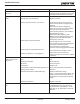
Castile Pellet Insert
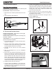
Base Plate Only Installation
Parts Needed: (1) cast ring (2) base zero clearance panel
extensions. Discard balance of parts.
Tools Needed: Phillips head screwdriver
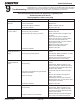
1. Attach base zero clearance panel extensions to cast
ring.
2. Place assembly under appliance.
Panel Extension
Panel Leg
Cast Trim Footer
Figure 21.1
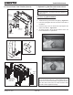
G. Surround & Trim Set, Econo
Back of Top Panel
Back of Side Panel
Screws
Included in Surround Kit:
2 side pieces, left and right,
top piece and fastener package.
Included in Basic Trim Kit: 2 side pieces, left and right, top
piece and “L” brackets.
Tools Needed: 4-6 inch long Philips head screwdriver,
pliers and fl at head screwdriver
1. Lay surround face down on a fl at protected surface
to prevent scratching.
2. Using the Philips head screwdriver attach the side
surrounds to the top surround using 2 sheet metal
screws provided with the kit on each side.
3. Assemble the trim with the two corner brackets
provided.
4. Slide the assembled trim over the assembled
surround set.
5. Remove the cast sides before attaching the surround
and trim. Lift up the top to expose the thumb screws
that secure the cast sides. Remove the thumb screw
and top bracket and then remove the cast side.
NOTE: The right cast side bracket has the hopper
cut out switch attached. Remove the retainer from
the right side and allow to hang down into the insert
or disconnect the switch when removing side.
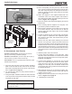
6. Install the power cord in the surround.
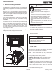
7. If power enters the appliance on the right side:
Using the pliers, attach cord restraint 12 inches from
the female end of the cord and then press into the
right side panel. Figure 21.2.
Figure 21.4
F. Hearth Support (Cont’d)
8. If power enters appliance on the left side: The cord will
have to be routed through the back of the insert. When
routing the power cord, keep cord lying fl at as possible,
keeping the cord away from all exhaust surfaces and
moving parts. After routing, install cord restraint and
press into the left side panel.
9. Slide surround over the top of the insert into
place.
Surround attaches to bottom and top of insert sides with
the supplies 1/4 inch screws.
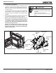
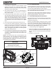
10. Plug cord into inlet on junction box routing the wire as
shown in Figure 21.3.
11. Install plug into unused hole.
12 in (305mm)
Figure 21.2
Plug Cord into Junction Box
Figure 21.3