
Owner`s manual


32 7036-187 January 29, 2014
MT. VERNON AE INSERT
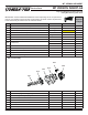
Input Line Voltage
AC out to Control
Board
15V DC out to
Control Board
Fuse
15A 250V
Power Supply shown with cover removed
Input Line
Voltage
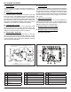
Heat sinks are taped to cover for shipping. Slowly lift cover
and cut the tape holding them in place and then you can
remove the cover.
17
1
2
3
4
5
6
7
8
910111213
14
15 16
n/a
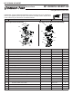
Fuse 15A 230V,
under the cover
Fuse 15A 230V,
under the cover
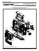
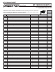
Figure 32.2 - Control Board
Figure 32.1 - Power Supply
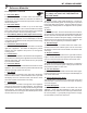
17. Power Supply
The power supply is located at the rear of the appliance. It
converts 120 volt AC current to 15 volt DC current to power
the appliance.
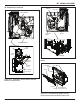
18.
Overheat Sensor (Snap Disc)
The overheat sensor is mounted on the back of the drop
tubeinthecenteroftheapplianceandhasaresetbutton.
Toaccessitremovetherightsidepanel.Iftheretriesto
burnbackintothefeedsystemorpushexhaustupthefeed
tube,thissensorwillshuttheappliancedown,howeverthe
wallcontrolwillstilldisplaymessages.Thissensormustbe
manuallyre-set.Disconnectpowerbeforeresetting.
19. Thermocouple - Firepot
This thermocouple is located on top of the repot inside
the thermocouple cover (ceramic protection tube). The
thermocouple sends a millivolt signal to the control board
tellingthecontrolboardthereisareintherepot.
20. Thermocouple - Drop Tube
This thermocouple is located on the bottom of the drop
tubeontherightsideandattachedwithawingnut.Itturns
the convection blower on and off,varies the speed of the
convection blower and will shut down appliance if internal
heat exceeds set temperature.
21. Vacuum Switch
The vacuum switch is located on the right side of the appliance
underthefeedmotorbehindrightsidepanelandconnectsto
thedroptubewithahose.Thisswitchturnsthefeedsystem
onwhenvacuumispresentintherebox.Thevacuumswitch
is a safety device to shut off the feed motor if the exhaust or
theheatexchangersystemisdirty,pluggedoriftherebox
door is open.
22. Wall Control Thermostat
The appliance is designed to run on a custom designed 3.3
volt DC thermostat wall control. It will not operate on any
other wall control. Refer to the instructions supplied with the
appliancelocatedinthecomponentpack.
23. Wiring Schematic for Power Supply
See Figure 32.1 below.
24. Wiring Schematic for Control Board
See Figure 32.2 below.
# Description
1 CombustionBlower
2 Auto-Clean System
3 Feed/AugerMotors
4 Hopper/DoorSwitches
5 Auger/Auto-Clean/Vacuum
Switches
6 Low Fuel
# Description
7 Thermostat Wall Control
8 CombustionBlower(feedback)
9 Firepot Thermocouple
10 DropTubeThermocouple
n/a Not Used
11 ConvectionBlower(feedback)
# Description
12 Igniter
13 AC Power In for Igniter
14 ConvectionBlowerPower
15 OverheatSensor(SnapDisc)
16 DC Power In from Power Supply
17 12VoltBatteryBack-up