
Indoor Fireplace User Manual


March 4, 2002 Page 12 30211C
DV400S DIRECT VENT ROOM HEATER
R
NOTE: For buildings with vinyl siding, a Vinyl
Siding Standoff should be installed between
the vent cap and the exterior wall. Attach
the Vinyl Siding Standoff to the Horizontal
Vent Termination. The Vinyl Siding Standoff
prevents excessive heat from possible melt-
ing the vinyl siding material. NOTE: The
HHW2 cap incorporates it's own vinyl siding
standoff. See Fig. 8.
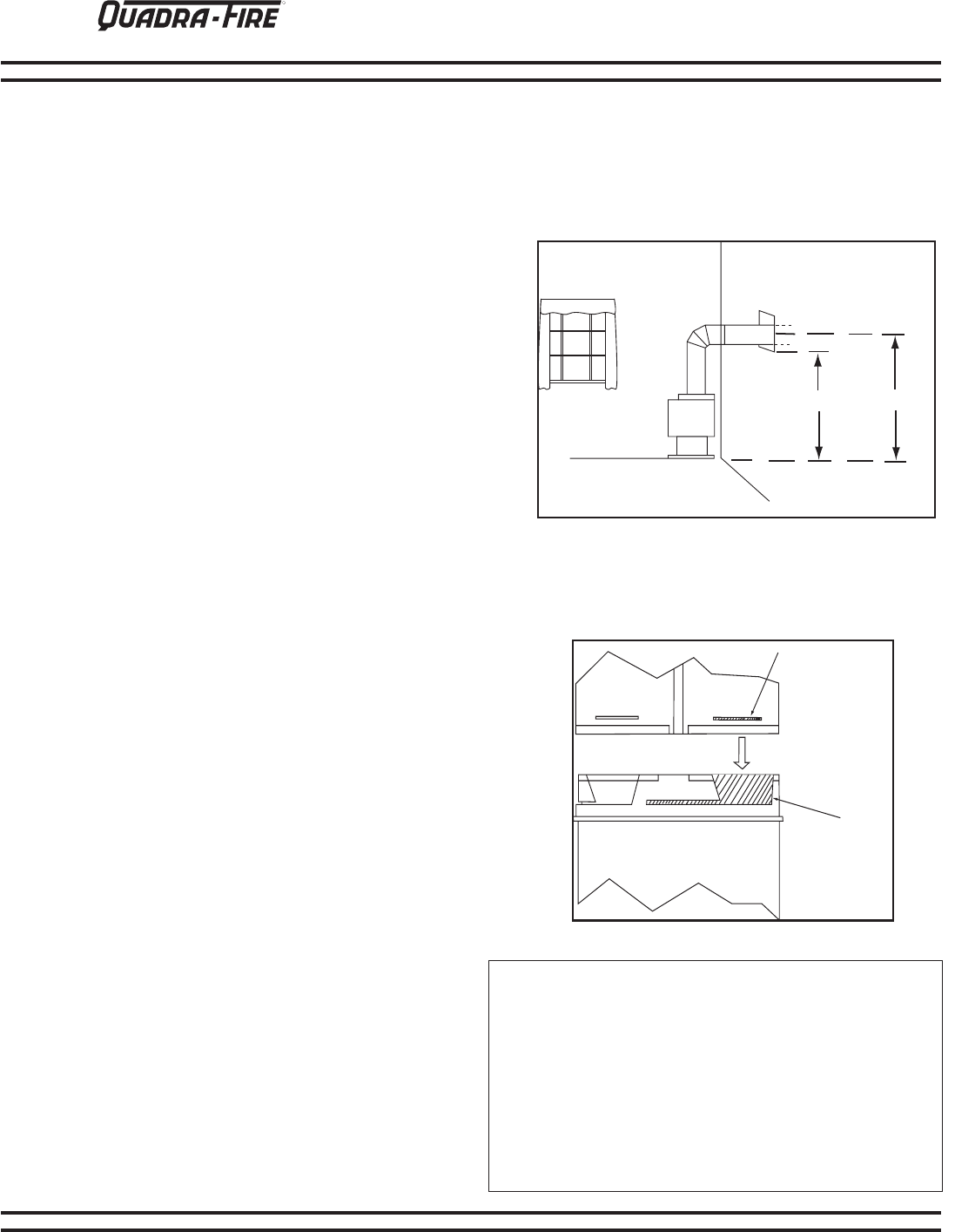
2. Assembling Venting Sections.
Use only vent supplied or listed for use with this
Heater. To attach a straight section to the top of
the Heater, female end down, slide the pipe over the
outer Collar on the Heater while the inner flue will slip
over the Vent Inner.
MAINTAIN MINIMUM CLEARANCES OR
GREATER AROUND THE VENT SYSTEM. Do not
pack air spaces with insulation or other material.
If the wall being penetrated is constructed of non-
combustible material (i.e.: masonry block or con-
crete) a 7 inch diameter hole is acceptable. It is
recommended that for masonry walls the vent be
wrapped with fiberglass insulation to prevent contact
with the masonry as the contact promotes premature
deterioration of the vent.
Figure 5 - Twist-lock procedure
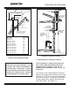
1. Preparing the Wall for Horizontal
Termination.
A hole measuring 10” wide and 10” high must be cut
and framed in the exterior wall where venting will be
terminated.
The height of the hole must be located to meet all
local and national codes and not be easily blocked
or obstructed. The minimum height to the center of
the horizontal vent is 59
1
/2'' from the base of the unit.
This figure will increase by the length of each verti-
cally positioned vent section added to the venting
system. See Figure 4.
Figure 4 - Exterior Wall Hole
EXTERIOR
WALL
HOLE TO BE
VENTED
THROUGH
10''x 10'' DURA-
VENT MINIMUM
54
1
/2''
59
1
/2''
Female
Locking
Lugs
Male
Locking
Lugs