R GARNET-T DIRECT VENT ROOM HEATER Owner’s Manual Installation and Operation Model: Tested and Listed by Portland Oregon USA O-T L C US OMNI-Test Laboratories, Inc. GARNET-MBK GARNET-D-MBK GARNET-D-PMH GARNET-D-CSB GARNET-D-CWL CAUTION DO NOT DISCARD THIS MANUAL • Important operating and • Read, understand and • Leave this manual with follow these instructions maintenance instructions party responsible for use for safe installation and included. and operation. operation.
and Welcome to the Quadra-Fire Family! Hearth & Home Technologies welcomes you to our tradition of excellence! In choosing a Quadra-Fire appliance, you have our assurance of commitment to quality, durability, and performance. This commitment begins with our research of the market, including ‘Voice of the Customer’ contacts, ensuring we make products that will satisfy your needs.
- TABLE OF CONTENTS Section 1: Listing and Code Approvals A. Appliance Certifications ......................4 B. Glass Specifications ............................4 C. BTU Specifications ..............................4 D. High Altitude Installations ....................4 E. Non-Combustible Materials .................4 F. Combustible Materials ........................4 G. Requirements for the Commonwealth of Massachusetts ......5 Section 2: Getting Started A. Design & Installation Considerations ............
1 Listing and Code Approvals C. BTU Speci cations A. Appliance Certi cation MODEL: Garnet-T Model (US or Canada) Maximum Input BTU Minimum Input BTU Orifice Size (DMS) *Steady State % **P.4 % LABORATORY: OMNI Test Laboratories, Inc. 061-S-35c-5 Garnet-T (NG) 17,000 12,000 49 76.93 67.38 TYPE: Direct Vent Gas Heater Garnet-T (LP) 17,000 13,000 56 78.19 69.52 STANDARD: ANSI Z21.88a-2003 CSA 2.33a-2003 UL307b CAN/CBA 2.
NOTE: The following requirements reference various Massachusetts and national codes not contained in this document. G.
2 Getting Started A. Design & Installation Considerations Quadra-Fire direct vent gas appliances are designed to operate with all combustion air drawn from outside of the building and all exhaust gases expelled to the outside. No additional air source is required. CAUTION Check building codes prior to installation. • Installation MUST comply with local, regional, state and national codes and regulations.
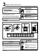
3 Appliance Location and Clearances NOTE: · Illustrations reflect typical installations and are FOR DESIGN PURPOSES ONLY. · Illustrations/diagrams are not drawn to scale. · Actual installation may vary due to individual design preference. WARNING Fire Risk Provide adequate clearance: • Around air openings • To combustibles • For service access Locate appliance away from traffic areas. A.
4 Termination Locations A. Vent Termination Minimum Clearances HORIZONTAL OVERHANG WARNING 2 FT. MIN. Fire Risk. Explosion Risk. Maintain vent clearance to combustibles as specified. 20 INCHES MIN. VERTICAL WALL LOWEST DISCHARGE OPENING GAS DIRECT VENT TERMINATION CAP • Do not pack air space with insulation or other materials. Failure to keep insulation or other materials away from vent pipe may cause fire. X 12 ROOF PITCH IS X/ 12 H (MIN.
M N P G R v A D H Q (See Note 2) E v V B L v v F v U.S. (3 FT) B B v V v I M A V = VENT TERMINAL A B D* = 12 inches ............. clearances above grade, veran(See Note 1) da, porch, deck or balcony = 12 inches ............ clearances to window or door that may be opened, or to permanently closed window. (Glass) = 18 inches ............. vertical clearance to unventilated soffit or to ventilated soffit located above the terminal *30 inches ............
5 Vent Information A. Venting Components B. Use of Elbows In order to comply with applicable codes and product warranties, use only following venting components: • • • • • CAUTION ALL vent configuration specifications MUST be followed. Hearth & Home Technologies (HHT) Simpson Dura-Vent Selkirk Direct-Temp Amerivent Direct Security Secure Vent • This product is tested and listed to these specifications. • Appliance performance will suffer if specifications are not followed.
D. How to Use the Vent Graph E. Venting Guidelines 1. NOTES The maximum horizontal vent run is 15 ft. (5m) when the vertical vent rise is 10 ft. (3m). 2. 3. Measure the vertical distance from the center line of the flue pipe to the center of the 90° elbow. On the graph below, draw a horizontal line from that measurement on the vertical axis across until it intersects with the slanted line. From the point of this intersection, draw a vertical line to the bottom of the graph.
F. Horizontal Termination Type A - Up & Out Installations for Top Vent Configurations Step 1. Determine the desired location of the appliance. Check to ensure that wall studs or roof rafters are not in the way when the venting system is attached. If this is the case, you may want to adjust the location of the appliance. WARNING 90º ELBOW center line TERMINATION CAP PIPE LENGTH Fire Hazard. Exhaust Fume Risk. Impaired Performance of Appliance.
codes, and must not be easily blocked or obstructed, see Figure 4.4 on page 9. WARNING Fire Risk. Explosion Risk. Combustion Fume Risk. Use vent run supports per installation instructions. Connect vent sections per installation instructions. • Maintain all clearances to combustibles. • Do NOT allow vent to sag below connection point to appliance. • Maintain specified slope (if required).
1/4 in. (6mm) 8 in. Fold Strap Here (203mm) 7 in. (178mm) 7 in. (178mm) Sheet Metal Screw 6 in. (152mm) Wall Thimble Wall Thimble Cover/Ceiling Firestop as Required by Local Jurisdiction Strap Figure 5.7 Figure 5.9 (NOTE: Some termination caps may cause the vent Note: The attachment from the vent pipe to the vent pipe to be off center on the flashing). Ensure that proper termination cap must be sealed with silicone. Termination clearances to combustible materials are maintained.
G. Vertical Termination WARNING 1. Direct Vent Pipe VERTICAL TERMINATION CAP STORM COLLAR Fire Risk. Explosion Risk. Maintain vent clearance to combustibles as specified. • Do not pack air space with insulation or other materials. Failure to keep insulation or other materials away from vent pipe may cause fire. FLASHING FIRESTOP SUPPORT BOX 25 ft. (8m) MAXIMUM PIPE LENGTH Figure 5.11 Figure 5.10 Step 1. Check the installation instructions for required 1 in.
necessary to reach from the ceiling support box/wall thimble up through the roof line. Galvanized pipe and elbows may be utilized in the attic, as well as above the roofline. The galvanized finish is desirable above the roofline, due to its higher corrosion resistance. NOTE: (1) If an offset is necessary in the attic to avoid obstructions, Plumber’s Tape connected to Wall Strap it is important to support the vent pipe every 3 ft. (914mm) to avoid excessive stress on the elbows, and possible separation.
Step 8. Slip the storm collar over the pipe, and push it down to the top of the flashing (Figure 5.15). Use non-hardening sealant above and below the joint between the storm collar and the pipe. Optional High Wind Termination Cap Secure Flashing with Non-Hardening Sealant and Roofing Nails WARNING Fire Risk. Explosion Risk. • Any occupied areas above the first floor, including closets and storage spaces, which the vertical vent passed through must be enclosed.
2. Cathedral Ceiling Step 1. Follow installation Steps 1 and 2 under vertical installation section, page 15. Step 2. Remove shingles or other roof covering as necessary to cut the rectangular hole for the support box. Cut the hole 1/8 in. (3mm) larger than the support box outline. Step 3. Lower the support box through the hole in the roof until the bottom of the support box protrudes at least 2 in. (51mm) below the ceiling (Figure 5.17). Align the support box both vertically and horizontally with a level.
Step 4. Pass the flex pipe down through the center of the chimney system, and center the top adapter on the top of the chimney pipe. Drill four 1/8 in. (3mm) diameter holes through the top adapter, and into the chimney top. Ensure that you are drilling into the metal on the chimney. Twist lock the high wind termination cap onto the top adapter (Figures 5.22 and 5.23). 3. Class A Metal Chimney TERMINATION CAP TOP ADAPTOR FLASHING EXISTING METAL CHIMNEY SYSTEM 4 in.
4. Existing Masonry Chimney Type A & B - Co-Axial to Co-Linear Type C - Up & Out Installation Type A TERMINATION CAP Chimney Liner Termination Cap 3 in. (76mm) Flex Liner Co-Axial to Co-Linear Connector TOP ADAPTOR RETRO CONNECTOR FLASHING 4 in. (102mm) FLEX LINER 90° ELBOW DIRECT VENT PIPE Pipe Length Optional Showing two 35 ft. (11m) Sections of Flex Liner Type D - Hearth Mount Type B Chimney Liner Termination Cap Chimney Liner Termination Cap 25 ft. (8m) of 3 in.
CAUTION Cut and bend flashing as needed to fit Ensure that existing chimney is functionally sound and clean. • Have inspection done by qualified chimney sweep or professional installer BEFORE converting to direct vent appliance. Step 1. Before cutting any holes, assemble the desired sections of direct vent pipe to determine the center of the masonry penetration. Sealant adhesive Figure 5.26 Step 2. Once the center point of the penetration has been determined, cut a 6 in.
Flex Liner 6 in. (152mm) diameter opening in masonry wall Flex Coupler Sheet Metal Screws Retro Connector Figure 5.27 (3) Masonry Bolts (Not included) Step 8. Secure the top adapter to the flashing. Use three sheet metal screws through the side of the top adapter into the flange on the flashing (Figure 5.28). Twist lock the high wind termination cap on to the top adapter. High Wind Termination Cap Figure 5.29 Step 10.
H. Slim Line Wall Thimble CAUTION Sharp Edges • Wear protective gloves and safety glasses during installation. BEFORE YOU BEGIN: Review the venting configurations in Figures A, B and C on the next page. Attach the heat shield to the trim ring with the four screws provided. Screws go through the heat shield and into the brackets on the trim ring. Figure 5.33 1. Assembling Slim Line Trim Ring and Heat Shield 2.
FIG. A 90 DEGREE ELBOW Use HEAT SHIELD or WALL THIMBLE Place mark where protrudes through exterior wall to cut off excess 90° ELBOW center line PIPE LENGTH PIPE LENGTH TRIM RING SOLID OR VENTILATED TERMINATION CAP FIG. B 45 DEGREE ELBOW NOTE: Wall Thimble removed TRIM RING to show Heat Shield HEAT SHIELD OVER PIPE 45° Elbow 2 in. (51mm) Clearance from stove corner to combustible wall 2 in. 951mm) Clearance from stove corner to combustible wall. FIG. C MINIMUM CLEARANCE MINIMUM OF 6 in.
6 Gas Information A. Fuel Conversions PILOT HOOD MILLIVOT GENERATOR Before making gas connections ensure that the appliance being installed is compatible with the available gas type. THERMOCOUPLE Any natural or propane gas conversions necessary to meet the appliance and locality needs must be made by a qualified technician using Hearth & Home Technologies specified and approved parts. 1.
with the kit. Tighten screws securely. (Reference torque = 25 in./lb.) Install the enclosed identification label (F) to the valve body where it can be seen. 2. Valve Regulator Replacement WARNING Fire Risk. Explosion Risk. • Disconnect any electrical cords and turn off gas supply to unit before proceeding if converting fuel on an appliance already fully installed. Remove upper and lower back shield. Loosen the set collars on the extension rods with the 3/32 in. Allen wrench.
B. Gas Pressures C. Gas Connection Proper input pressures required for optimum appliance performance, gas line sizing requirements need to be followed from NFPA51. WARNING Fire Risk. Explosion Hazard. High pressure will damage valve. • Disconnect gas supply piping BEFORE pressure testing gas line at test pressures above 1/2 psig. • Close the manual shutoff valve BEFORE pressure testing gas line at test pressures equal to or less than 1/2 psig.
WARNING Fire or Explosion Hazard • Gas build-up during line purge may ignite. • Purge should be performed by qualified technician. • Ensure adequate ventilation. • Ensure there are no ignition sources such as sparks or open flame. • A small amount of air will be in the gas supply lines. When first lighting appliance it will take a short time for air to purge from lines. When purging is complete the appliance will light and operate normally.
7 Electrical Information A. Recommendation for Wire See B5 below for recommended maximum lead length (two wire) when using wall thermostat/switch. NOTE: This appliance must be electrically wired and grounded in accordance with local codes or, in the absence of local codes, with National Electric Code ANSI/NFPA 70-latest edition or the Canadian Electric Code, CSA C221.1. 8. Ensure the thermostat is mounted level for accurate readings. 9.
Thermopile Pilot Igniter Thermocouple PILOT ASSEMBLY IGNITION MODULE TPTH Black TP ON/OFF Switch Black TH VALVE Figure 7.1 CAUTION CAUTION Label all wires prior to disconnection when servicing controls. Wiring errors can cause improper and dangerous operation. Verify proper operation after servicing. Page 30 Shock hazard. • Replace damaged wire with type 105O C rated wire. • Wire must have high temperature insulation.
8 Appliance Setup A. Remove Shipping Materials C. Flue Restrictor Installation Remove shipping materials from inside or underneath the firebox. When your installation falls within a shaded area on the vent graph (page 11) a ue restrictor must be installed for proper operation. B. Leg Leveling System Thread Allen bolts through nuts until flush. The Allen bolts and nuts are included in the component pack inside the appliance firebox. Figure 8.
D. Accessories Install approved accessories per instructions included with accessories. Refer to Section 12 for appropriate accessories. WARNING Shock or fire risk. Use ONLY optional accessories approved for this appliance. • Using non-listed accessories voids warranty. • Using non-listed accessories may result in a safety hazard. • Only Hearth & Home Technologies approved accessories may be used safely. Align left front log with notch in burner and notch on rear log. Figure 8.7 E.
G. Glass Replacement Turn the appliance OFF and let it cool down before replacing the glass. Lift off the appliance top and place it on a flat surface, with the porcelain side up, to prevent damage. Remove the appliance front by sliding it upward in the grooves, being careful not to chip the porcelain. Lay the front face up on a flat surface. Unhook latch now exposed on top of the appliance. Pull the top of the glass frame towards you and lift it out of the retainer along the bottom of the firebox.
SNAP DISC SNAP DISC BRACKET SPADE TERMINALS Figure 8.12 Install the snap disc. A snap disc bracket is located in the appliance's component bag. Bend the two spade teminals on the snap disc from a horizontal to a vertical position. Insert the snap disc through the hole in the snap disc bracket and attach the two white wires from the wiring harness to the snap disc. Install the speed control (rheostat). The speed control mounts to the decorative cover previously removed.
Thermal Disc WHITE BLACK WHITE Fan Speed Control BLACK GREEN Ground Strain Relief Bushing BLACK WHITE Power Cord (110 VAC) BLACK Fan Assembly Figure 8.
I. Ignition Module Access and Battery Replacement OPEN CLOSE Loosen the wingnut that secures the damper. The wingnut is located on the underside of the appliance, to the right of the pilot assembly. Figure 8.17 To CLOSE the intake damper, pull the wingnut forward toward the front of the appliance.. Figure 8.16 The ignition module is located under the appliance attached to the decorative cover. To OPEN the damper, push the wingnut back. Adust the damper in 1/4 in.
9 Operating Instructions A. Before Lighting Appliance Read this entire manual prior to using the appliance. Failure to follow the instructions may result in property damage, bodily injury, or even death. • Remove all shipping materials from inside and/or underneath the firebox. • Review proper placement of logs, mineral wool. • Check the wiring. • Check the baffle adjustment. • Ensure that there are no gas leaks. • Ensure that the glass is sealed and in the proper position.
C. Lighting Appliance FOR YOUR SAFETY READ BEFORE LIGHTING WARNING: If you do not follow these instructions exactly, a fire or explosion may result causing property damage, personal injury or loss of life A. This appliance has a pilot that must be lit manually. When lighting the pilot, follow these instructions exactly. B. BEFORE LIGHTING, smell around the appliance area for gas. Be sure to smell next to the floor because some gas is heavier than air and will settle on the floor.
D. After Appliance is Lit CAUTION Initial Break-in Procedure When you light your appliance, you may notice that it produces heat which does have an associated odor or smell. If you feel this odor is excessive it may require the initial three to four hour continuous burn on high followed by a second burn up to 12 hours to fully drive off any odor from paint and lubricants used in the manufacturing process. Condensation on the glass is normal.
10 Troubleshooting With proper installation, operation, and maintenance your gas appliance will provide years of trouble-free service. If you do experience a problem, this troubleshooting guide will assist a qualified service person in the diagnosis of a problem and the corrective action to be taken. This troubleshooting guide can only be used by a qualified service technician. Symptom 1. After repeated triggering of the piezo button, the spark ignitor will not light the pilot. 2.
Symptom 3. (Continued) Possible Cause Corrective Action c. Defective valve. Turn the valve knob to the ON position. Place the ON/OFF switch in the ON position. Check the millivolt meter at the thermopile terminals. The millivolt meter should read greater than 125mV. If the reading is acceptable, and if the burner does not come on, replace the gas valve. d. Plugged burner orifice. Check the burner orifice for stoppage. Remove stoppage. e. Wall switch or wires are defective.
11 Maintaining and Servicing Your Appliance Although the frequency of your appliance servicing and maintenance will depend on use and the type of installation, a qualified service technician should perform an appliance check-up at the beginning of each heating season. CAUTION Handle glass assembly with care. NOTE: Clean glass after initial 3-4 hours operation. Longer operation without cleaning glass may cause a permanent white lm on glass. WARNING Risk of injury or property damage.
A. Maintenance Tasks Inspect Doors Maintenance Tasks 1. Inspect for scratches, dents or other damage and repair as necessary. 2. Verify no obstructions to air flow. 3. Verify maintenance of proper clearance to combustible household objects. Gasket Seal, Glass Assembly and Glass 1. Inspect gasket seal and its condition. 2. Inspect glass for scratches and nicks that can lead to breakage when exposed to heat. 3. Confirm there is no damage to glass or glass frame, Replace as necessary. 4.
12 Reference Materials A. Appliance Dimension Diagram Dimensions are actual appliance dimensions. Use for reference only. For clearances refer to Section 3. D C A B E F Figure 12.
B. Vent Components Diagram 6-3/8 in. (162mm) 6-1/2 in. (165mm) 9-1/4 in. (235mm) 6-1/2 in. (165mm) 6-3/8 in. (162mm) 6-5/8 in. (168mm) 9-5/8 in. (244mm) SLP45-BK 6-5/8 in. (168mm) 9-5/8 in. (244mm) SLP90M 17-24 in. (432-610mm) 6-1/2 in. (165mm) 11-3/4 in. (298mm) SLP12AM 5-3/4 in. (146mm) 6-5/8 in. (168mm) SLP12M SLP6M 47-3/4 in. (1213mm) 35-3/4 in. (908mm) 23-3/4 in. (603mm) 12-17 in. (305-432mm) 3-3/4 in. (95mm) SLP4M SLP6AM SLP24M SLP36M SLP48M 4 in. (102 mm) inner pipe 6-5/8 in.
C.
Description 45° Elbow, Swivel, Black 90° Elbow, Galvanized 90° Elbow, Black HHT SL-P M= Multi Pack (6) Simpson ® Dura-Vent DirectVent Pro - 46DVA-E45B SLP90M See Swivel Selkirk ® Direct-Temp Amerivent ® Direct Security ® Secure Vent - - SV4EB45 4DT-EL905 4D90LS - SLP90-BK See Swivel 4DT-EL90SB 4D90LBS SV4EBR90 90° Elbow, Swivel, Galvanized - 46DVA-E90 - - SV4E90 90° Elbow, Swivel, Black - 46DVA-E90B - - SV4EB90 Adjustable Flashing, 0/12-6/12 SLP-RF6M 46DVA-F6 4DT-AF6 4D
R D.
R D. Service Parts List (cont’d.) (NG, LP) Exploded Parts Diagram GARNET-T Beginning Manufacturing Date: 6-16-04 Ending Manufacturing Date: IMPORTANT: THIS IS DATED INFORMATION. The most current information is located on your dealer's VIP site. When ordering, supply serial and model numbers to ensure correct service parts. Item # Part Description Alphabetical Order Part # Adapter, DV (6-5/8 in.
R D. Service Parts List (cont’d.) (NG, LP) Exploded Parts Diagram GARNET-T Beginning Manufacturing Date: 6-16-04 Ending Manufacturing Date: IMPORTANT: THIS IS DATED INFORMATION. The most current information is located on your dealer's VIP site. When ordering, supply serial and model numbers to ensure correct service parts.
R E. Accessories (NG, LP) Exploded Parts Diagram GARNET-T Beginning Manufacturing Date: 6-16-04 Ending Manufacturing Date: IMPORTANT: THIS IS DATED INFORMATION. The most current information is located on your dealer's VIP site. When ordering, supply serial and model numbers to ensure correct service parts.
F.
G.
G.
H. Warranty Policy R Lifetime Warranty LIMITED LIFETIME WARRANTY The Hearth & Home Technologies limited Lifetime Warranty guarantees that the following components will work as designed for the lifetime of the stove or Hearth & Home Technologies will repair or replace them.
I. Contact Information R CONTACT INFORMATION: Hearth & Home Technologies 1445 North Highway Colville, WA 99114 Division of HHT INDUSTRIES Please contact your Quadra-Fire dealer with any questions or concerns. For the number of your nearest Quadra-Fire dealer please visit our web site at www.quadrafire.com CAUTION Do NOT discard this manual. • Important operating and maintenance instructions included. • Read, understand and follow these instructions for safe installation and operation.