
Specifications
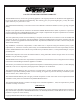

Grand Bay 40 Direct Vent Freestanding
Page 31January 2000
VERTICAL TERMINATIONS (cont.)
INSTALLATION INTO AN EXISTING MASONRY CHIMNEY (cont.)
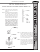
FIG. 25
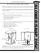
Step 7. If additional lengths of flex liner are
needed to span the chimney height, use
a flex coupler to connect the pieces of
flex liner together. Connect the flex to
the coupler by using four sheet metal
screws for each side (Figure 25).
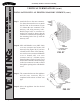
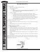
Step 8. Secure the top adapter to the flashing.
Use three sheet metal screws through the
side of the top adapter into the flange on
the flashing (Figure 26). Twist lock the
high wind termination cap (SDV #991)
on to the top adapter.
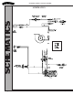
Step 5. Connect the flex liner to the top adapter
using three sheet metal screws (see
Figure 20).
Step 6. Feed the flex liner through the flashing
into the chimney. Carefully feed the flex
liner down the chimney to the bottom
and out the opening in the masonry wall,
forming an angle to line up the flex liner
with the vent opening on the appliance.
NOTE: Do not let the flex liner sag
below the level at which it will connect
to the appliance or connector. This
could allow hot gas to become trapped
and potentially become a fire hazard.
The flex liner path should always be
sloped up toward the termination cap.
FIG. 26
TOP ADAPTER