
Installation manual


June 19, 2014 7034-277C 13
MT. VERNON AE
A
C
B
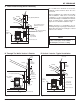
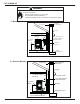
5 Venting Systems
NOTE:
• Illustrations refl ect typical installations and are FOR
DESIGN PURPOSES ONLY.
• Illustrations/diagrams are not drawn to scale.
• Actual installation may vary due to individual design
preference.
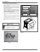
A. Alcove
Figure 13.1
*All minimums listed are to a combustible surface.
Minimum* Maximum
Inches Millimeters Inches Millimeters
A
Height 43 1092 n/a n/a
B
Width 40 1016 n/a n/a
C
Depth n/a n/a 36 914
D
To Side Wall 6 152 n/a n/a