
Owner`s manual


R
November 5, 2014
7014-188G
Page 9
1200-I Pellet Insert
NOTE:
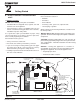
• Illustrations refl ect typical installations and
are FOR DESIGN PURPOSES ONLY.
• I
llustrations/diagrams are not drawn to
scale.
• Actual installation may vary due to
individual design preference.
B. Clearance To Combustibles, UL and ULC
12 in.
(305mm)
Rear Shroud
6 in.
(152mm)
Shown with Hopper Extended
Optional Outside
Air
Combustible
Mantel
INSTALLED AS A BUILT-IN UNIT
Shown with Rear Vent and Optional Outside Air
Figure 9.1
Figure 9.2
AS A BUILT-IN
B
D
C
E
B
C
A
0 INCH (0mm) CLEARANCE TO EXPOSED SECTION AND FACE TRIM
Rear Shroud Kit is Required for Built-In Installation
A Top of Shroud Top Vent 3.0 76
Rear Vent 0 0
B Sides of Inside Shroud Top or Rear Vent 0 0
C Back of Inside Shroud Top Vent 2.5 64
Rear Vent 0 0
D Vent Pipe to Combustible Top or Rear Vent 3.0 76
E From Outside Edge of
Panel Set to Combustibles
0 0
Inches Millimeters
Fire Risk.
WARNING
Failure to comply may cause house fi re.
Comply with all minimum clear-
ances to combustibles as specifi ed.
NOTICE:
Please note that while the minimum clear-
ance for the termination cap is 6 inches
(152mm) there is the possibly of soot
buildup around the termination area. If this
occurs we suggest to move the termination
further away from the house to prevent it.