
Owner`s manual


Page 24
7075-166C
May 23, 2013
R
er
. u e e e e e e
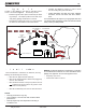
Figure 2.3
5HPRYLQJ7XEH&KDQQHO$VVHPEO\
1. Remove the 3 right side bricks.
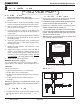
5HPRYHWKHEDIÀHSURWHFWLRQFKDQQHOE\EHQGLQJEDFNWKHWDEV
using needle nose pliers located at the right and left side of the
protection cover. Lift the cover up slightly and pull toward the
IURQWDQGRXWRIWKH¿UHER[Figure 2..
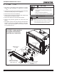
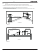
3. Locate the 2 channel nuts and two bolts inside of chamber and
remove using a 7/16 socket wrench. Figure 2.2.
: Soak the bolts with penetrating oil for at least 15 minutes
before trying to remove them.
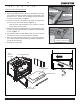
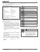
4. Slide the tube channel assembly all the way to left until it is off the
threads. Drop the right side down, then slide the assembly back
to right. Figure 2.3.
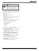
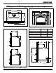
7KHFHUDPLFEODQNHWDQGERWKEDIÀHERDUGVFDQEHUHPRYHGDW
the same time you remove the tube channel assembly.
6. When the tube channel assembly is free of the left side sup-
SRUWURWDWHFORFNZLVHDQGSXOODVVHPEO\EODQNHWDQGEDIÀHVRXW
through the front opening.
7. Re-install in reverse order.
Baffle Protection
Channel
Bend Back Tabs
Use 7/16 Socket Wrench
and Remove Channel Nuts
Figure 2.
Figure 2.2
Tube
Channel
Assembly
2 Tube Channel Nuts
Ceramic Blanket
Baffle
Protection Channel
2 Baffle Boards