
Specifications


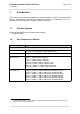

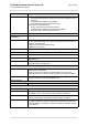
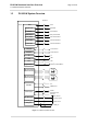
Table Of Contents
- Contents
- Tables
- Figures
- 1 Introduction
- 2 Interface Characteristics
- 3 Operating Characteristics
- 4 Mechanical Dimensions, Mounting and Packaging
- 5 Regulatory and Type Approval Information
- 6 Document Information

PLS63-W Hardware Interface Overview
1.2 Key Features at a Glance
11
Page 8 of 48
GSM/GPRS/EGPRS features
Data transfer GPRS:
• Multislot Class 12
• Mobile Station Class B
• Coding Scheme 1 – 4
EGPRS:
• Multislot Class 12
• EDGE E2 power class for 8 PSK
• Downlink coding schemes – CS 1-4, MCS 1-9
• Uplink coding schemes – CS 1-4, MCS 1-9
• SRB loopback and test mode B
• 8-bit, 11-bit RACH
• 1 phase/2 phase access procedures
• Link adaptation and IR
• NACC, extended UL TBF
• Mobile Station Class B
SMS Point-to-point MT and MO
Cell broadcast
Text and PDU mode
Storage: SIM card plus SMS locations in mobile equipment
GNSS Features
Protocol NMEA
Modes Standalone GNSS (GPS, GLONASS, Beidou, Galileo)
General Automatic power saving modes.
DC feed bridge and control of power supply for active antenna
Software
AT commands
Hayes 3GPP TS 27.007, TS 27.005
SIM Application Toolkit Default (Network) bearer support for BIP
Firmware update Generic update from host application over USB modem
Interfaces
Module interface Surface mount device with solderable connection pads (SMT application
interface). Land grid array (LGA) technology ensures high solder joint reli-
ability and allows the use of an optional module mounting socket.
For more information on how to integrate SMT modules see also [4].This
application note comprises chapters on module mounting and application
layout issues as well as on additional SMT application development equip-
ment.
USB USB 2.0 High Speed (480Mbit/s) device interface. Full Speed (12Mbit/s)
compliant.
Feature Implementation