
User's Manual

©QTI Page Revision: F
Form #: 30Z0138 Effective Date: 24 August 2006
3
Section 1: EMIDS Receiver Operational Mode
A receiver during normal operation will receive and decode any messages on a selectable channel. The message will be
displayed as two-digit (MIDS message) or three-digit (EMIDS message).
Status indicators will also be displayed with any EMIDS message received. This information may also be sent through the
RS232 serial port to a remote computer/terminal.
FEATURES:
Displays either MIDS or EMIDS messages.
Stores the last 10 messages received in memory for later recall.
Available in three frequency ranges Low, Mid, and High:
Low Band: 138.025-153.000 MHz @ 25 kHz steps
Mid Band: 154.005-162.000 MHz @ 5.0 kHz steps
High Band: 162.00625-174.000 MHz @ 6.25 kHz steps
May operate on one of up to 1920 channels depending on frequency range.
Low Band: 600 channels (001-600)
Mid Band: 1600 channels (001-1600)
High Band: 1920 channels (001-1920)
ID codes may be locked out as individual ID codes or as a group of sequential
codes (duty gate during hours of operation), up to 9 groups can be locked out.
(Either MIDS or EMIDS).
Audio level can be adjustable during operation, set to a fixed level, or turned off.
A short audio tone (EMIDS only) indicates a status only message, a long audio
tone indicates active alarm message.
Backlight level may be off or fixed to one of nine levels.
Serial interface with selectable baud rates. Many of the features may be
controlled by a computer/terminal.
Potted and sealed electronic components.
Injection molded lexan plastic housing.
Metal battery cap clamps with heat welded screw inserts.
Frequency matched antenna.
Sealed battery compartment.
RS232 data port for interfacing with a computer. (Setup receiver as a base
station receiver. Receiver MIDSComm software and receiver cable required.)
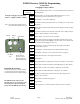
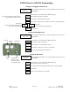
Receiver Menu
The Menu is accessed from the Off state. Hold the push button down and rotate the On/Off Volume knob
clockwise. The receiver will turn On, and be in the Menu mode.
CHn – sets the received channel number
LO – sets the lockouts
AUd – sets the level of the audio
bl – sets the backlight level
SEr – sets the serial port parameters
ON/OFF Volume Control
During Normal Operation the volume knob is used to turn the receiver on and off, and to adjust the audio level of the
piezo (if adjustable audio is selected).
During Menu Mode the volume knob is used to display the desired menu item.
Push Button
During Normal Operation the push button will light the backlight for 4 seconds on the first push (if the backlight is
enabled), on the next push of the button (while backlight is on) the contents of memory [0] will be displayed, the next push
of the button (while memory [0] is still displayed) will display memory [1] and so on through memory [9]. Memory [0]
will always contain the last message received. To clear the current display, push the button and hold it in, while tilting the
receiver slightly past horizontal.
During the Menu Mode the push button is used to select the desired menu item.
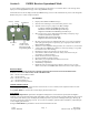
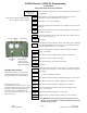
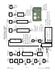
Antenna
Push Button
RS232
Port
Ear Phone
Jack
On/Off Switch
Volume Control
Menu Selection &
Programming Knob