
User's Manual

©QTI Page Revision: F
Form #: 30Z0138 Effective Date: 24 August 2006
7
EMIDS Receiver (MMCR) Programming
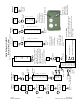
LOCKOUTS
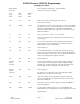
Changing Group Lockouts
Press and hold the push button in. Turn the ON/OFF switch clockwise to
the ON position.
Release Button – (If already in Menu Mode disregard). To select
Lockouts (LO) rotate knob until the “LO” appears.
Press button – “On” will be displayed.
To enable lockouts press button when “On” is displayed – “LO1” will be
displayed.
Rotate knob until the desired lockout group is displayed. In this example
it is LO2.
To enable lockouts in LO2 rotate the knob until “On” is displayed. Press
button – display changes to current setting.
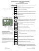
Rotate knob to current Low ID – Press button.
Rotate knob until the first number of the NEW Low ID of the group is
displayed (if using standard MIDS it will be a blank, to set a black rotate
the knob clockwise slightly past the “9”)
Press button – set the second number by rotating the knob until the
desired number appears.
Press button – rotate knob until the last desired number appears.
Press button – ID 24 is now set as the low ID in the LO2 group.
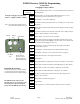
Rotate the knob back to LO2 and press the button.
Press button.
If the old high ID is not displayed, rotate the knob until it is. Press button.
Rotate knob until the first number of the High ID appears. Press button.
Rotate knob until the second number is displayed – press button.
Rotate knob until the third number is displayed – press button.
If “End” is not displayed rotate the knob until “End” appears. Press
button – return to menu.
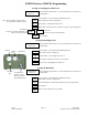
Rotate knob until “End” is displayed.
Press button.
Operating mode – “Lockouts Enabled” shown top center of display.
Button held in
Power On
Chn
LO
LO2
On
LO1
024
0
_
_
LO2
0--
01
-
010
LO4
150
Lockouts
Enabled
Chn
End
100
10
-
1
--
End
The MMCR must be returned to the
operating mode to save the changes. The
saved changes now become the default
settings when the MMCR is powered up.
Individual ID Lockouts
Follow the same steps as group lockouts,
except the desired lockout (ID Code) is
inserted in both the low and high settings.
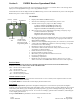
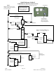
Antenna
Push Button
RS232
Port
Ear Phone
Jack
On/Off Switch
Volume Control
Menu Selection &
Programming Knob
Note: The push button prompt means to
press the button and then release it.
Example: Changing LO2 group from
024 (Lo) – 250(hi) to 010(Lo) – 100(hi)