
User's Manual


QTI Page 3 of 15 Revision: C
Form #: 30Z0266 Effective Date: 5 October 2012
Section 1: MCDR Multi-Channel Data Receiver
Description
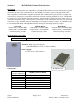
The Multi-Channel Data Receiver (MCDR) is an OEM modular modem for users who need low power
and small size with serial communications. The MCDR is a smaller version of the MCDT-R and is
fully compatible. The MCDR is equipped with a RS-485 communications port which is a simple, low-
cost interface, utilizing few components and allows for daisy-chaining multiple receivers. The MCDR
is capable of receiving SEIWG-005 data messages, which includes a distinct ID and a status code, over
a selectable frequency range. This frequency is selectable via the synthesizer control circuit, providing
a selection of up to 1920 RF channels, depending on the model’s frequency range. The MCDR comes
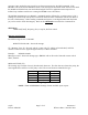
in Low-Band, Mid-Band, and High-Band models, having the following frequency ranges:
Low Band Medium Band High Band
Channel 001 = 138.025 MHz Channel 001 = 154.005 MHz Channel 001 = 162.00625 MHz
Channel 640 = 154.000 MHz Channel 1600 = 162.000 MHz Channel 1920 = 174.000 MHz
Channel Spacing: 25 kHz Channel Spacing: 5 kHz Channel Spacing: 6.25 kHz
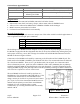
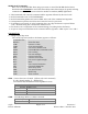
Model Numbers (3 models)
10D1068-L, -M, -H MCDR-L, -M, -H MCDR Receiver only; low, mid, or high band
Antenna: MMCX jack 50 ohm (J1)
(10D1984 MMCX to TNC 3” cable available)
Power Supply:
3.5 VDC to 16.5 VDC Receive
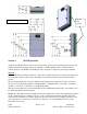
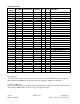
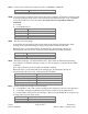
Connections:
J2 - Header Pin
(10-pin TFM-105)
MCDR_ Receiver Model
1, 2 Vin [Input] 3.5 to 16.5 VDC
3 Not Used
4 RS485 – B(+) [I/O]
5 RS485 – A(-) [I/O]
6 Same as pins 1,2
7 General I/O
8, 9, 10 GND
MCDR Receiver