
User's Manual


QTI Page 4 of 15 Revision: C
Form #: 30Z0266 Effective Date: 5 October 2012
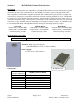
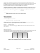
Current Draw Approximations:
Mode Current Comments
Sleep 20uA MCDR wakes up on RS485 bus activity
Active 5.0mA Receiver off / Microprocessor on
Receiver On 35mW @ 3.5VDC
165mW @ 16.5VDC
Receiver on – Waiting for valid RF message
Receiver Active 16.9mA RF message received – Microprocessor on
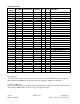
Design Features
ID Code Selection 000-999 for EMIDS, 000-063 for all other formats
Directional, sensor fault, low battery, tamper, and test status codes for EMIDS format
Able to receive and transmit MIDS 20-bit or MMIDS / EMIDS 29-bit messages
MMCX antenna port matched to 50 ohms
Conformal-coated and shielded circuit assembly
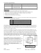
Physical Characteristics
The MCDR is light weight and comes in a compact size. This makes it ideal for mobile applications as
well as applications with tight space constraints.
Receiver Only
Weight 40 g (1.4 oz)
Height 14.4 mm (0.565 in) (0.739 in w/standoffs)
Length 56.4 mm (2.219 in)
Width 34.4 mm (1.355 in)
The shielding on the MCDR has been designed in a way to promote easy PCB integration. The top of
the MCDR is equipped with three alignment tabs that can be used as standoffs. By utilizing these pins
and a proper connector, you are able to design a board that will hold the MCDR. Dimensions for the
MCDR are shown in Figures 2 below.
Connections to the MCDR can be made by connecting to the J2 header and the J1 MMCX jack. The
header used on the MCDR is SAMTEC part TFM-105-XX-X-D. The recommended mate is SFM-105-
T2-L-D-P from SAMTEC. These are 2 x 5 pin headers with a 50 mil pitch. See Connections table
above to determine pin outs. Qual-Tron offers a MMCX to TNC cable (10D1984), but any industry-
standard, gold-plated MMCX plug should mate to the jack adequately. Carefully aligning and gently
rotating the MMCX plug in the jack helps reduce both the possibility of damage to either connector as
well as the force required to connect or disconnect.
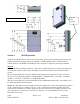
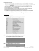
The serial RS485 I/O driver IC used by Qual-tron is a
MAXIM part. The part number is MAX3471EUA+. If the
customer also includes this IC from MAXIM in their
design, connect pin 6 of the IC to pin 4 on J2 and connect
pin 7 to pin 5 on J2. Note: Sometimes RS485 devices are
marked with the polarity reversed from normal RS485
standards. If a new or unknown device cannot
communicate, try reversing the differential lines usually
marked A & B.
Figure 1. RS485 Circuit