
User's Manual


QTI Page 5 of 15 Revision: C
Form #: 30Z0266 Effective Date: 5 October 2012
Section 2: MCDR Operation
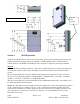
Using the settings provided in Section 3: Serial Interface, open a serial communication program such
as HyperTerminal and supply power to the MCDR. A USB to RS485 cable is available that can
connect directly to the MCDR. The USB port from a computer is capable of powering the MCDR.
Start Up
When the MCDR is initially powered on, a “BL<CR>” output string is sent to indicate the opportunity
for entering the “Boot Loader” mode. The ability to enter the boot loader mode will timeout after 1
second.
The next serial output that is sent after the BL timeout indicates the reason for the reset or restart. It
can be one of the following messages: "PWR-ON RST", "EXT RST PIN", "COP RST", "ILLEGAL
OP RST", "ICG RST", "LVD RST", or "UNKNOWN RST".
After the reset message, the version information is sent “MCDR 029A 003G<CR>” for example. (See
the VER command for the description).
NOTE: The “BL” (Boot Loader) response provides the opportunity to enter the programming mode for
one (1) second at start up. Sending a “P” (no “<CR>”) will enter the firmware upgrade mode and
could cause the firmware to be erased. Therefore, the user is advised not to send any characters to the
unit, especially not a character “P” followed by a character “Y” to the MCDR before the version
information is received.
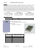
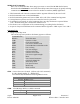
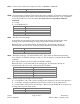
Figure 2. MCDR Receiver
FCC ID
Label
Location