
User's Manual


QTI Page 6 of 15 Revision: D
Form #: 30Z0250 Effective Date: 1 August 2010
Section 2: MCDT Operation
Using the settings provided in Section 3: Serial Interface, open a serial communication program such
as HyperTerminal and supply power to the MCDT. A USB to RS485 cable is available that can
connect directly to the MCDT. The USB port from a computer is capable of powering the “receiver
only” version. However, it is not recommended that the MCDT “transmitter only” and transceiver units
be powered from the USB port. The current draw during the initial super-capacitor charging period and
during transmission may cause damage to the cable and/or computer.
Start Up
When the MCDT is initially powered on, a “BL<CR>” output string is sent to indicate the opportunity
for entering the “Boot Loader” mode. The ability to enter the boot loader mode will timeout after 1
second.
The next serial output that is sent after the BL timeout is the reason for the reset or restart. It can be
one of the following messages: "PWR-ON RST", "EXT RST PIN", "COP RST", "ILLEGAL OP
RST", "ICG RST", "LVD RST", or "UNKNOWN RST".
After the reset message, the version information is sent “MCDT 028A 003G<CR>” for example. (See
the VER command for the description).
NOTE: The “BL” (Boot Loader) response provides the opportunity to enter the programming mode for
one (1) second at start up. Sending a “P” (no “<CR>”) will enter the firmware upgrade mode and
could cause the firmware to be erased. Therefore, the user is advised not to send any characters to the
unit, especially not a character “P” followed by a character “Y” to the MCDT before the version
information is received.
Receiving/Transmitting
During normal operation, the MCDT is capable of sending and receiving SEIWG-005 messages via the
serial port and via radio frequency. The MCDT assumes a low-power shut-down mode to conserve
power when not in use.
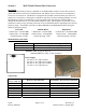
ITEMS REQUIRED
1. DC Power Source: 4.0 to 16.5 Volts
2. Personal Computer with USB or RS232 port
3. 10-pin connector to RS-485 USB cable (QTI part# 10D1978)
4. Serial Communications Program such as HyperTerminal
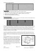
SETUP
1. Set the Channel. (Default CHR 001)
2. Enable receiver, if desired. Transmit is always enabled. (Default RCV 1)
3. Enable Push to send messages out serial port, or disable to poll for messages. (Default PSH 1)
RF Link
The operational range of the RF link is dependent upon various conditions. The high frequency of the
RF link works best under line of sight conditions. RF range may vary from 0.5 kilometer to 5
kilometers for open areas using the 1-Watt setting. Greater range may be expected using the 2-Watt
setting.