
User Manual

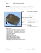

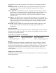


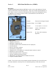
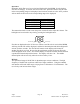
Table Of Contents
- Description
- Design Features
- Operation
- ID Switch Setting Chart
- Sensor Connection
- RF Link
- Emplacement Considerations
- Section 2:MIDS Remote Control Transmitter (MRCT)
- Frequency Range:138-174 MHz
- Section 3:MIDS Hand Held Receiver (MPDM)
- Section 4:MIDS Remote Control Receiver (MRCR)
- Pin Connector:A: Ground
- Section 5:Frequency/Channel Calculations

ID Switch Setting Chart
ID
x8 x1
ID
x8 x1
ID
x8 x1
ID
x8 x1
00
0 or 8 0 or 8
16
2 0 or 8
32
4 0 or 8
48
6 0 or 8
01
0
or 8 1 or 9
17
2 1 or 9
33
4 1 or 9
49
6 1 or 9
02
0 or 8 2
18
2 2
34
4 2
50
6 2
03
0
or 8 3
19
2 3
35
4 3
51
6 3
04
0 or 8 4
20
2 4
36
4 4
52
6 4
05
0
or 8 5
21
2 5
37
4 5
53
6 5
06
0 or 8 6
22
2 6
38
4 6
54
6 6
07
0
or 8 7
23
2 7
39
4 7
55
6 7
08
1 or 9 0 or 8
24
3 0 or 8
40
5 0 or 8
56
7 0 or 8
09
1
or 9 1 or 9
25
3 1 or 9
41
5 1 or 9
57
7 1 or 9
10
1 or 9 2
26
3 2
42
5 2
58
7 2
11
1
or 9 3
27
3 3
43
5 3
59
7 3
12
1 or 9 4
28
3 4
44
5 4
60
7 4
13
1
or 9 5
29
3 5
45
5 5
61
7 5
14
1 or 9 6
30
3 6
46
5 6
62
7 6
15
1
or 9 7
31
3 7
47
5 7
63
7 7
The MRCT selector switches use octal numbering system. 1-7 are their shown value.
The number ‘8’ has a value of ‘0’ and the number ‘9’ has a value of ‘1’.
RF Link
The operational range of the RF link is dependent upon various conditions. The high
frequency of the RF link works best under line of sight conditions. Transmission can
range from hundreds of yards to several miles, depending on terrain. The transmission
range can be extended with the use of relays, or by elevating the antenna at either the
transmitter or receiver position.
Emplacement Considerations
The MRCT is a hand held unit only.
QTI Page 8 Revision: C
Form #: 30Z0147 Effective Date: 24 August 2006