Terrestrial Mobile Communications Terminal Installation Instructions 80-53184-1 Rev.
QUALCOMM Incorporated 5775 Morehouse Drive San Diego, CA 92121-1714 Copyright © 1990–1999 QUALCOMM Incorporated. All rights reserved. Printed in the United States of America. OmniTRACS® and QUALCOMM® are registered trademarks and registered service marks of QUALCOMM Incorporated. SensorTRACS®, JTRACS®, JTRACS Pro®, and TrailerTRACS® are registered trademarks of QUALCOMM Incorporated. QUALCOMM Wireless Business Solutions™ is a trademark of QUALCOMM Incorporated.
Contents Product Overview 1 Tools and Supplies Needed for Installation 1 Installation Overview 2 Typical TMCT System Installation Sequence 3 Typical Installation Location 4 TCU Antennae Installation 4 Orienting and Installing the TCU Antennae on the Tractor Roof 4 GPS Antenna Mounting Procedures 6 PCS Antenna Mounting Procedures 6 EDU and Holster Installation Procedures 7 Selecting a Location 7 Installing the EDU Holster 7 Inspecting Cables 9 Connecting the EDU Cable to the EDU 9 Inserting the EDU into t
iv QUALCOMM Proprietary 80-53184-1 Rev.
Terrestrial Mobile Communications Terminal Installation Instructions Product Overview The Terrestrial Mobile Communications Terminal (TMCT) is the complete cost-effective mobile information management solution for vehicles operating in metropolitan areas and major highway corridors. The system provides two-way communications, automatic position reports, and collects and records powerful management data.
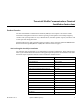
Installation Overview Terrestrial Mobile Communications Terminal Installation Instructions Drill Bits • Silicone Sealant • 3/8” Bit • Loctite 242 (blue) • 5/16” Bit • Assorted Ring Terminals 5/8” Bit and 3/4” Bit (both are available on 1/43/4 step/index drill bit) • Red, Blue, & Yellow Butt Splices • 1-1/2” Hole Saw • Electrical Tape Air Tools Test Light • 3/8” Drill Flash/Drop Light 3/8” Ratchet Power Tools Note: The tools marked with a bullet (•) are considered essential.
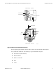
Terrestrial Mobile Communications Terminal Installation Instructions Installation Overview COE truck cab - top view EDU PCS Antenna GPS Antenna Handset Handset and EDU Cable TCU PCS Antenna GPS Antenna Antenna Cable EDU TCU Handset COE truck cab - side view 99AAB_01 Typical TMCT System Installation Sequence Before beginning the installation, plan the order in which you will install the TMCT System. Every installation is different. The following is a typical installation sequence: 1.
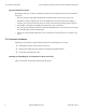
TCU Antennae Installation Terrestrial Mobile Communications Terminal Installation Instructions Typical Installation Location Depending on the type of vehicle, installation locations for the components will vary (see illustration on page 3). • The TCU Antennae (GPS and PCS) should be mounted securely to the exterior tractor roof.
Terrestrial Mobile Communications Terminal Installation Instructions TCU Antennae Installation GPS antenna PCS antenna 99AAB_04 Follow these steps to orient and install the antennae: 1. The location of the GPS and PCS antennae should be along the front outer edge of the trailer roof as close to the center nose as possible. 2. Before drilling holes, verify that cable routing will adequately reach the bottom of the TCU where the connection is required. 3.
TCU Antennae Installation Terrestrial Mobile Communications Terminal Installation Instructions GPS Antenna Mounting Procedures 1. After orienting the antenna, drilling the 1-inch diameter hole, and cleaning the surface with alcohol, remove the liner from the bottom of the antenna. 2. Route the cable through the mounting hole. 3. Position the GPS antenna over the mounting hole and adhere. Ensure that the adhesive mates to the top surface. 4.
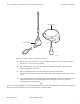
Terrestrial Mobile Communications Terminal Installation Instructions EDU and Holster Installation Procedures EDU and Holster Installation Procedures Selecting a Location The EDU has a 15-line LCD screen and a holster that holds and protects the unit when it’s not in use. The most common holster installation location is the dashboard, closer to the passenger-side seat (see the following illustration).
EDU and Holster Installation Procedures Terrestrial Mobile Communications Terminal Installation Instructions If you do not use the backing plate: a. Verify that there is nothing behind the mounting surface that might be damaged by the screws. b. Install the screws. Be careful not to damage the holster or mounting surface by overtightening the screws. If you do use the backing plate: c. Verify that the rear of the mounting surface is accessible and that there is enough space for the backing plate. d.
Terrestrial Mobile Communications Terminal Installation Instructions EDU and Holster Installation Procedures Straight Bent 2. Remove the protective caps on the connectors only when you are ready to connect the cable to the TCU and the display unit. Protective cap installed on connector Connecting the EDU Cable to the EDU Follow these steps to connect the EDU Cable to the EDU: 1. To open the access door at the back of the EDU, press the two snaps that hold the door in place and lift the door.
EDU and Holster Installation Procedures Terrestrial Mobile Communications Terminal Installation Instructions Grommet Enhanced Display Unit (EDU) 10-8575-1 3. Make sure the rubber grommet fits in the grooves of the unit and that the flat side of the grommet on the cable is facing up. 4. To secure the cable, close the access door, inserting the tabs at the bottom first. Use the provided hardware to fasten the door shut.
Terrestrial Mobile Communications Terminal Installation Instructions Handset Installation Handset Installation Selecting a Location The Handset includes a cradle that holds and protects the phone when not in use. The most common installation location is on the dashboard, closer to the driver’s side of the cab.
TCU Installation Terrestrial Mobile Communications Terminal Installation Instructions Antenna (P1) Handset (J9) Display (J8) Power (J7) 99AAB_05 Selecting a Mounting Location If possible, install the TCU behind the driver’s seat on the cab wall. 12 QUALCOMM Proprietary 80-53184-1 Rev.
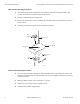
Terrestrial Mobile Communications Terminal Installation Instructions TCU Installation To Antenna Driver’s Seat To power, display and handset units U TC r we Po y pla Dis r t ve se dri nd a d H in eh ll b a nw na ten An do nte U TC u mo Cab exterior 99AAB_06 80-53184-1 Rev.
TCU Installation Terrestrial Mobile Communications Terminal Installation Instructions Location and Orientation • Choose a location where the unit will not come into contact with liquids or solvents. • Choose a location where tire chains or other tools will not likely be stowed on top of the unit or cables. Do not mount the unit near items that may fall on it or bump cable connections. • Choose a location that is structurally sound.
Terrestrial Mobile Communications Terminal Installation Instructions Cable Installation Connecting the Power/Accessory Connector to the TCU After you have installed all other connectors, plug the Power/Accessory connector into the appropriate slot. Tighten the screwlocks on the connector securely. Checking All TCU Cable Connections • Check to make sure all cable connections are securely tightened. Check that all cables have service loops and that they are free from interference.
Cable Installation Terrestrial Mobile Communications Terminal Installation Instructions 2. Excess cable can be stored neatly coiled near the TCU, usually under the driver’s seat. Installing the EDU Cable The EDU Cable connects the EDU to the TCU. Cable Run Run Direction - In most vehicles, the EDU is mounted on the dashboard. The cable is routed from the front of the vehicle toward the back to the TCU (usually mounted behind the driver’s seat).
Terrestrial Mobile Communications Terminal Installation Instructions Cable Installation 3. Plug the Handset connector into the appropriate slot of the TCU. Installing the Power/Accessory Cable The Power/Accessory Cable connects the TCU to the vehicle’s electrical power source. Cable Run Run Direction - The Power/Accessory Cable can be routed from front to back or back to front. The direction depends on whether the access hole is big enough for the connector (1-1/4 inches).
Cable Installation Terrestrial Mobile Communications Terminal Installation Instructions You may connect the accessory wire (green wire labeled “lights”) if you install an optional accessory such as the Remote Message Waiting Light, Buzzer, or Pager. Follow these steps to connect the Power/Accessory Cable wires: 5. The yellow wire labeled +12 VDC BTRY (pins A & B) is for the unswitched (main) 12 VDC connection.