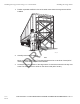
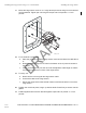
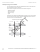
Installing the Cargo Sensor Using 3" or 1" Pan Mount Position a portable scaffold in front of the trailer nose where the cargo sensor will be installed. AF T 1. Installing the Cargo Sensor 04AAA_131 Carefully ascend the scaffolding. R 2. Note D Mount on the bay next to the TT210 terminal which will be on the driver’s side (left of center) no closer than 18" to the trailer sidewall. 3. 11-4 Rev. A Locate the mounting position of the cargo sensor.
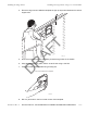
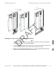
Installing the Cargo Sensor Place the cargo mount installation template as high up as practical between the vertical support rails. AF T 4. Installing the Cargo Sensor Using 3" or 1" Pan Mount 10AAA_02 Secure the template with two self-drilling screws through holes in the handle. 6. Using the template as a guide, drill the 18 stud holes using a 3/8" drill. 7. Trace the inside of the template using a felt-tip pen. D R 5. Trace the inside of the template 10AAA_04 8. 80-J7615-1 Rev.
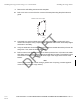
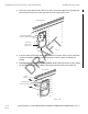
Installing the Cargo Sensor Using 3" or 1" Pan Mount 9. 10. Installing the Cargo Sensor Remove the self-drilling screws and the template. Drill a 7/8" hole on each of the four corners of the template using the pilot holes as a guide. Drill four 7/8" corner holes AF T Scribed Line Completely cut out the marked area for the cargo sensor with a cutting tool, being careful not to drop the newly cut panel inside or outside of the trailer. Avoid sharp edges and debur if necessary. 12.
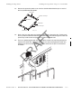
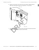
Installing the Cargo Sensor 14. Installing the Cargo Sensor Using 3" or 1" Pan Mount Remove the protective plastic cover from the double-sided adhesive tape on each of the four prefabricated stud plates. Stud Plate Double-sided Tape Stud Plate Stud Plate Double-sided Tape Stud Plate 04AAA _135A Each of the four stud plates are installed on the inside of the trailer skin. Position each to line up with the stud holes that were just drilled.
Installing the Cargo Sensor Using 3" or 1" Pan Mount Mount the cargo sensor to the 3" or 1"cargo sensor pan mount using four lock nuts and four flat washers. Tighten just until snug and torque to 20 inch-pounds +/- 5 inchpounds. AF T 17. Installing the Cargo Sensor 10AAA_010A For a container or plate nose: Place the grommet around the cargo sensor connector and down the cable about 9". b. Route the cable through the 7/8" hole in the bottom of the 3" pan and connect to the sensor. c.
Installing the Cargo Sensor Installing the Cargo Sensor Using a Flat Internal Mount Dry Van Use 3" or 1" Pan Internal Wiring Plate Nose and Containers Use 3" Pan External Wiring Plate Nose AF T Container R Installing the Cargo Sensor Using a Flat Internal Mount Note D Mount on the bay next to the TT210 terminal which will be on the driver’s side (left of center) no closer than 18" to the trailer sidewall. 1. Locate the mounting position of the cargo sensor.
Installing the Cargo Sensor Using a Flat Internal Mount 3. Installing the Cargo Sensor Center the cargo sensor side to side in the hole. The bottom edge of the plywood hole should be a minimum of 6” below the lower lip of the cargo sensor cone. Trailer Exterior Cargo Sensor Mount Riveted to Trailer skin AF T Cut Interior Plywood for Cargo sensor 10AAA_48 Trailer Skin From the inside of the trailer, while holding the mount in place, drill four 3/16” rivet holes.
Installing the Cargo Sensor 6. Installing the Cargo Sensor Using a Flat Internal Mount Attach the cargo sensor to the cargo sensor mount using the supplied hardware. Tighten just until snug and torque to 20 inch-pounds +/- 5 inch-pounds. Interior view Exterior Mounted Terminal AF T Dual Cargo Sensor 10AAA_21A1 Route and connect the cargo sensor cable. Ensure that the cable does not block the cargo sensor or is visible in the cone area. Secure cable. D 7. R Interior Plywood 80-J7615-1 Rev.
TT210 System Cargo Sensor Validation Installing the Cargo Sensor TT210 System Cargo Sensor Validation The TT210 system terminal’s cargo sensor default setting will “wake up” the cargo sensor every 30 minutes and check for a cargo load. This is customer configurable. The terminal can be customer configured to: • Message immediately • Send on next report • Respond to a ping • Ignore An ultrasonic sensor detects objects approximately 20 feet back from the nose of the trailer.
12 Installing the Swing Door Sensor Introduction This chapter provides guidelines and instructions for installing the TT210 system trailer swing door sensor. AF T Topics in this chapter include: Swing Door Sensor Installation Overview . . . . . . . . . . . . . . . . . . . . . . . . . . . . . . . Swing Door Sensor Validation . . . . . . . . . . . . . . . . . . . . . . . . . . . . . . . . . . . . . . . . Swing Door Sensor Installation . . . . . . . . . . . . . . . . . . . . . . . . . . . . . . . . . . . .
Swing Door Sensor Installation Overview Installing the Swing Door Sensor Swing Door Sensor Installation Overview The swing door sensor kit contains the swing door sensor (with magnet and switch) and an 85-foot door sensor cable assembly. (The replacement swing door sensor kit comes without the 85-foot cable assembly.) The door sensor cable assembly can be routed two ways: • Externally, under the trailer up to the TT210 system mount assembly (along the same route as the factory wiring and/or brake lines).
Installing the Swing Door Sensor Swing Door Sensor Installation Swing Door Sensor Installation The recommended external installation procedure is to route the door sensor cable underneath the trailer from the trailer nose where the TT210 system mount assembly is located, to the rear where it will connect with the swing door sensor. The cable can route along the left side, right side, or center underneath the trailer. Note The entire length of the 85-foot cable is covered with convoluted tubing.
Swing Door Sensor Placement Installing the Swing Door Sensor Swing Door Sensor Placement 1. With the door open, use a felt-tip pen to mark a horizontal reference line on the door post in the area where the sensor will be located. Qualcomm recommends you locate the swing door sensor 2" above the bottom right side door hinge area where the door seal ends. Mark the post 2" above the lower right door hinge with the door open on the panel that faces inside when the door is open. AF T approx. 2.
Installing the Swing Door Sensor Swing Door Magnet Installation Swing Door Magnet Installation 1. Open the door. 2. Drill a 3/8" diameter x 7/8" deep hole along the horizontal line at the centerline of the door width. Note The 3/8" hole diameter is critical for proper magnet installation. Centerline of the door width AF T Drill 3/8"hole approximately 7/8" deep Door Seal 05AAA_235 Apply a generous amount of adhesive/sealant into the 3/8" hole in the door. 4.
Swing Door Sensor Installation Installing the Swing Door Sensor Swing Door Sensor Installation 1. Remove the taillight assembly from the trailer’s passenger side. Most taillight assemblies are held into place by a large rubber grommet. 2. Using a center punch, mark a spot on the door post to line up with the horizontal line and the middle of the door when the door is closed. This is where the switch will be located. 3. Drill a 1/2" hole at this point in the door post.
Installing the Swing Door Sensor 5. Testing the Swing Door Sensor Apply adhesive/sealant to the sensor and inside the hole in the door post. AF T Adhesive/Sealant 05AAA_229 6. Press the sensor all the way into the 1/2" hole until it is fully seated. 7. Wipe off any excess adhesive/sealant. R Testing the Swing Door Sensor Attach an ohmmeter to the sensor wires. 2. Close the door and check the ohmmeter for proper swing door sensor operation. D 1.
Swing Door Sensor Installation Verification Installing the Swing Door Sensor Swing Door Sensor Installation Verification 1. At the back of the trailer, butt splice the white sensor wires to the orange and yellow cable wires. Add additional strain relief by following the procedure on page 3-7. Slide convoluted tubing onto sensor wires, making sure to also cover the butt splices. Store excess wire behind the taillight assembly. 2. Replace the taillight assembly.
Installing the Swing Door Sensor Internal Cable Installation Procedure Internal Cable Installation Procedure The recommended internal installation procedure is to route the door sensor cable along the trailer “ceiling” from the trailer nose where the TT210 system mount assembly is located, to the rear where it will connect with the swing door sensor. Note The entire length of the 85-foot cable is covered with convoluted tubing. If there is any excess cable, cut the excess cable and discard.
Swing Door Sensor Placement Installing the Swing Door Sensor Swing Door Sensor Placement 1. With the door open, use a felt-tip pen to mark a horizontal reference line on the door post in the area where the sensor will be located. It is recommended you locate the swing door sensor 2" above the bottom right side door hinge area where the door seal ends. Mark the post 2" above the lower right door hinge with the door open on the panel that faces inside when the door is open. AF T approx. 2.
Installing the Swing Door Sensor 2. Swing Door Sensor Placement With the door closed, mark a horizontal reference line on the door and door post so the sensor and magnet can be easily aligned. AF T Trace the edge of the door onto the door post. Approximately an 18" high vertical line. Door Post Cargo door closed D R 05AAA_236B 80-J7615-1 Rev. A MAY CONTAIN U.S.
Swing Door Magnet Installation Installing the Swing Door Sensor Swing Door Magnet Installation 1. Open the door. 2. Drill a 3/8" diameter x 7/8" deep hole along the horizontal line at the centerline of the door width. Note The 3/8" hole diameter is critical for proper magnet installation. Centerline of the door width AF T Drill 3/8"hole approximately 7/8" deep Door Seal 05AAA_235 Apply a generous amount of adhesive/sealant into the 3/8" hole in the door. 4.
Installing the Swing Door Sensor Swing Door Sensor Installation Swing Door Sensor Installation 1. Remove the taillight assembly from the trailer’s passenger side. Most taillight assemblies are held into place by a large rubber grommet. 2. Using a center punch, mark a spot on the door post to line up with the horizontal line and the middle of the door when the door is closed. This is where the switch will be located. 3. Drill a 1/2" hole at this point in the door post.
Testing the Swing Door Sensor 5. Installing the Swing Door Sensor Apply adhesive/sealant to the sensor and inside the hole in the door post. AF T Adhesive/Sealant 05AAA_229 6. Press the sensor all the way into the 1/2" hole until it is fully seated. 7. Wipe off any excess adhesive/sealant. R Testing the Swing Door Sensor 1. Attach an ohmmeter to the sensor wires. 2. Close the door and check the ohmmeter for proper swing door sensor operation.
Installing the Swing Door Sensor Swing Door Sensor Installation Verification Swing Door Sensor Installation Verification 1. At the back of the trailer, butt splice the white sensor wires to the orange and yellow cable wires. Add additional strain relief by following the procedure on page 3-7. Slide convoluted tubing onto sensor wires, making sure to also cover the butt splices. Store excess wire behind the taillight assembly. 2. Replace the taillight assembly. Yellow Orange 3.
Installing the Swing Door Sensor D R AF T Swing Door Sensor Installation Verification 12-16 Rev. A MAY CONTAIN U.S.
13 Installing the Roll Door Sensor Introduction This chapter provides guidelines and instructions for installing the TT210 system trailer roll door sensor. AF T Topics in this chapter include: Roll Door Sensor Installation Overview . . . . . . . . . . . . . . . . . . . . . . . . . . . . . . . . . Roll Door Sensor Validation . . . . . . . . . . . . . . . . . . . . . . . . . . . . . . . . . . . . . . . . . . Roll Door Sensor Installation . . . . . . . . . . . . . . . . . . . . . . . . . . . . . . . . . . .
Roll Door Sensor Installation Overview Installing the Roll Door Sensor Roll Door Sensor Installation Overview The roll door sensor kit contains the rear door switch with attached 3-foot cable assembly, a magnet, and an 85-foot door sensor cable assembly. (The replacement roll door sensor kit comes without the 85-foot cable assembly.
Installing the Roll Door Sensor Roll Door Sensor Installation Roll Door Sensor Installation The recommended external installation procedure is to route the door sensor cable underneath the trailer from the trailer nose where the TT210 system mount assembly is located, to the rear where it will connect with the roll door sensor. The cable can route along the left side, right side, or center underneath the trailer. Note The entire length of the 85-foot cable is covered with convoluted tubing.
Roll Door Sensor Installation Installing the Roll Door Sensor Roll Door Sensor Installation 1. With the trailer roll door closed, use a felt-tip pen to draw a line along the inside of the passenger side of the door, close to door jamb. 2. Open the trailer roll door and position the roll door sensor switch as close as possible to the door jamb to avoid damage to the door sensor cable when loading the trailer. Take into consideration that the door sensor cable has a bend radius of two inches.
Installing the Roll Door Sensor Position the roll door sensor switch and mark the holes for the roll door sensor switch using a 3/16" drill bit. AF T 4. Roll Door Sensor Installation 06AAA_211a 5. Remove the taillight assembly from the trailer’s passenger side. Most taillight assemblies are held into place by a large rubber grommet. D R Rubber Seal Retainer Taillight Assembly 6. 80-J7615-1 Rev.
Roll Door Sensor Installation 7. Installing the Roll Door Sensor Drill a 1/2” hole at this point in the trailer floor. AF T Drill a 1/2" hole, approximately 5/8" minimum in from marked reference line and as close into the corner as possible. Take care to drill straight down. 5/8" 06AAA_217 Feed the sensor cable leads through the 1/2” hole and out the bottom of the trailer floor into the area behind the taillight. D R 8. Feed the armored cable down into the 1/2" drilled hole. 13-6 Rev.
Installing the Roll Door Sensor 9. Position the roll door sensor on the trailer floor to be aligned with the vertical reference line you marked. Secure the roll door sensor in place with the self-drilling screws. Pilot holes may be required. AF T 10. Roll Door Sensor Installation D R Use self-drilling screws to anchor the sensor. 2" Cable Radius Self-drilling Screws 80-J7615-1 Rev. A 06AAA_211 MAY CONTAIN U.S.
Roll Door Magnet Installation Installing the Roll Door Sensor Roll Door Magnet Installation Note The bottom of the trailer door may have a metal strip. Placement of the magnet may pitch the angle of the magnet forward over the roll door sensor switch. As long as the magnet is positioned within one inch of the top of the roll door sensor switch, the roll door sensor will operate properly.
Installing the Roll Door Sensor Roll Door Magnet Installation AF T Mark the horizontal location for mounting the magnet. 06AAA_215 0.75 Open and secure the door part way. 3. Position the magnet within the reference lines. 4. Secure the magnet using the self-drilling screws. D R 2. With the roll-up door open, install the magnet with the self-drilling mounting screws. 06AAA_213 80-J7615-1 Rev. A MAY CONTAIN U.S.
Roll Door Magnet Installation 5. Installing the Roll Door Sensor Close the trailer door and ensure the sensor switch and magnet are aligned. Ensure also there is some clearance between the sensor switch and the magnet. Magnet 06AAA_212 AF T Carefully close the roll-up door, and check to be sure there is some clearance between the sensor and the magnet. Roll-up Door 0.75 " 2.0" min R . D SENSOR 06AAA_207 13-10 Rev. A MAY CONTAIN U.S.
Installing the Roll Door Sensor Testing the Roll Door Sensor Testing the Roll Door Sensor 1. Attach an ohmmeter to the sensor wires. 2. Close the door and check the ohmmeter for proper roll door sensor operation. • When the door is closed, the ohmmeter should measure 0 ohms. D R AF T • When the door is open, the ohmmeter should measure infinite resistance.
Testing the Roll Door Sensor Installing the Roll Door Sensor Magnet AF T Sensor D R From Sensor From Terminal FLUKE 77 III 0 RANGE MULTIMETER 10 20 30 HOLD mV V A OFF A 300 mA 10 A V COM Doors Open 13-12 Rev. A 06AAA_216 MAY CONTAIN U.S.
Installing the Roll Door Sensor Roll Door Sensor Installation Verification Roll Door Sensor Installation Verification 1. At the back of the trailer, butt splice the white sensor wires to the orange and yellow cable wires. Add additional strain relief by following the procedure on page 3-7. Yellow Orange AF T When the test is completed and the circuit tests O.K. , splice the sensor wires to the terminal wires. 05AAA_246A Note The sensor is a simple switch device; polarity does not matter. 2.
Roll Door Sensor Installation Verification 4. Installing the Roll Door Sensor At the front of the trailer, butt splice the orange and yellow cable wires to the orange and yellow TT210 system door sensor wires at the TT210 system terminal. To TT210 System Mount Assembly Orange Yellow Orange AF T Yellow To Door Sensor 06AAA_222 Note The sensor is a simple switch device; polarity does not matter.
Installing the Roll Door Sensor Roll Door Sensor Installation Verification If you have technical questions about installing the TT210 system roll door sensor, please contact QES Customer Support: D R AF T In the United States, call 800-541-7490; in Canada, call 800-863-9191. 80-J7615-1 Rev. A MAY CONTAIN U.S.
Installing the Roll Door Sensor D R AF T Roll Door Sensor Installation Verification 13-16 Rev. A MAY CONTAIN U.S.
14 Installing the Auxiliary Sensor Introduction AF T The TT210 auxiliary sensor wires are available on the TT210 power/accessory cable assembly. This sensor option allows customers to use a third-party sensor with the TT210 system. The TT210 AUX sensor input is designed to detect digital (on/off switch) signals only. The TT210 system can be configured to generate alerts when an input transitions from high to low or from low to high. Topics in this chapter include: R Overview . . . . . . . . . . . . . .
Overview Installing the Auxiliary Sensor Overview The TT210 tire pressure sensor kit (65-J7313-1) contains the following components: • 20-foot AUX sensor extension cable assembly with convoluted protective tubing • AUX relay • Self-drilling hex washer-head screws • Black cable ties • Yellow inline, step-down butt splices • Blue insulated butt splices • Blue #10 ring terminal connectors The AUX relay should be installed next to the TT210 system inside the trailer.
Installing the Auxiliary Sensor 2. Tire Pressure Sensor Kit Installation Once the TT210 system diagnostic cable connector is located, connect Configuration tool?? software application. figure o ko Ba taD H to yS cn C c la E arr dn yM dA rd sse Po da S ce ru G far yti itif .n E px ne es M me 321 R MO arT lia M rP sfe AF T c ba 05AAA_262b Perform a TT210 system verification to ensure the TT210 system is functioning properly prior to installing the tire pressure sensor kit.
Tire Pressure Sensor Kit Installation Installing the Auxiliary Sensor Note The tire pressure light wire colors may vary from trailer to trailer. D R Black and white wires on the AUX sensor extension cable butt-spliced to the tire pressure warning light wires. AF T AUX sensor extension cable-tied to the trailer. 14-4 Rev. A Red PWR (power) wire and black GND (ground) wire on the AUX relay butt-spliced to the white and black wires on the AUX sensor extension cable.
Installing the Auxiliary Sensor 10. Wiring Schematic Using blue or pink splices, connect the two gray wires coming from the AUX relay to the two gray AUX_SENSOR wires on the TT210 system power/accessory cable (will be near the TT210 system terminal). Refer to the wiring schematics in this document. Wiring Schematic Schematic B Wiring Schematic A In this wiring configuration, the AUX relay is wired directly to the tire pressure warning light.
Tire Pressure Sensor Kit Validation Installing the Auxiliary Sensor Tire Pressure Sensor Kit Validation A simple opened/closed switch detects tire pressure. The validation time is set up per the customer’s request and state change reports are sent to the customer, as shown in the following illustration. TT210 System AUX Sensor Validation Open Closing Validation Time Note: FST s/w forces 5-second check interval.
Installing the Auxiliary Sensor Parameter Defaults Parameter Defaults Settings displayed in the following table are specific to the tire pressure sensor application. Other applications may require different initial and operational settings.
Installing the Auxiliary Sensor D R AF T Parameter Defaults 14-8 Rev. A MAY CONTAIN U.S.
15 Performing System Verification Introduction to System Verification This chapter describes the TT210 system verification process and basic diagnostic procedures. AF T Topics in this chapter include: D R What Is TT210 System Verification? . . . . . . . . . . . . . . . . . . . . . . . . . . . . . . . . . . . 15-2 TT210 System Verification . . . . . . . . . . . . . . . . . . . . . . . . . . . . . . . . . . . . . . . . . . . 15-2 Diagnostic Flowchart—TT210 System Verification . . . . . . . . . . . . . .
What Is TT210 System Verification? Performing System Verification What Is TT210 System Verification? The TT210 system verification is a functional system check that should be performed after installation of the TT210 system and after service to verify the TT210 system is operating properly. The chapters following this System Verification chapter provide the diagnostics steps necessary to resolve any problem that appears during the system verification.
Performing System Verification Diagnostic Flowchart—TT210 System Verification Diagnostic Flowchart—TT210 System Verification Step 1 Ensure all electrical connections are made. Step 8 Step 2 Connect PDA with FST software to 9-pin diagnostic connector. Turn on PDA and launch T2 FST software. Tap the [connect] icon Did it connect? No Go to chapter 24; AUX Sensor. Yes Step 9 No Go to chapter 20; FST Will Not Connect.
Diagnostic Flowchart—TT210 System Verification Performing System Verification Continued from Step 12 on the previous page. With only solar Step 13 power applied (no 7-way power), does the FST No s/w indicate the battery is charging and does Ext. Power indicate Solar between 4-6 volts? Step 18 Yes Go to chapter 34; Solar Power Go to chapter 34; Reefer Diagnostics: Reefer Data section.
Performing System Verification TT210 System Verification Procedure TT210 System Verification Procedure The steps in this procedure match the steps on the preceding system verification flowchart. The steps are not always sequential—you may be instructed to skip steps. 7.5 amp Fuse Blue (PWR) Pin 7 1. White (GND) Pin 1 Ensure that the following electrical connections are made: BLU BLK BR GR YEL NOTE: External power should not be applied to the TT210 system terminal until step 13.
TT210 System Verification Procedure Performing System Verification 2. Connect the TT210 system terminal to a laptop on which the Configuration tool software has been installed. • The serial cable connects to the 9-pin diagnostic connector on the TT210 system power/accessory cable. ??? To launch the TT210 Configuration tool software, double click the TT210 configure icon on the laptop Data Book Calc Address HotSync Graffiti Expense Memo Pad Prefs ROM Tran..
Performing System Verification TT210 System Verification Procedure 3. Tap . Please allow up to two minutes for the Configuration tool software to connect. Did the Configuration tool software connect to the TT210 system terminal? • If YES, go to step 4. • If NO, the failure to connect Alert screen will appear. Tap OK to clear the Alert screen. Check cable connections and tap again. Does the Configuration tool software connect now? - If YES, go to step 4.
TT210 System Verification Procedure Performing System Verification 4. If this is a new installation, the Configuration tool software will prompt you to enter the trailer ID. Qualcomm recommends that the trailer ID be set at this time. (This process associates the trailer ID with the TT210 system terminal’s ID in the customer’s account.) For detailed information regarding entering the trailer ID, refer to the TT200/TT210 Configuration Tool Quick Reference, 80J7595-1.
Performing System Verification TT210 System Verification Procedure 6. Cargo Sensor verification. If a cargo sensor is installed on the trailer, verify it is functioning correctly by toggling the current state. AF T NOTE: How to Toggle the Cargo Sensor If the trailer is empty, block the cargo sensor by holding a piece of cardboard approximately 6 inches from the cargo sensor. Confirm the cargo sensor state changes from Empty to Loading or Loaded.
TT210 System Verification Procedure Performing System Verification 7. Door Sensor verification. If a door sensor is installed on the trailer, verify it is functioning correctly by toggling the current state. NOTE: How to Toggle the Door Sensor If the trailer door is closed, open it. Confirm the door sensor state changes from Closed to Opening or Open. If the trailer door is open, close it. Confirm the door sensor state changes from Open to Closing or Closed.
Performing System Verification TT210 System Verification Procedure 9. Verify the GPS/Ant. status is OK—2D (good) or 3D (best) Fix. D R AF T • If YES, go to step 10. • If NO, GPS/Ant. is No Fix, go to Chapter 21: TT210 System Diagnostics: GPS No Fix. 80-J7615-1 Rev. A MAY CONTAIN U.S.
TT210 System Verification Procedure Performing System Verification 10. Make sure no external power (i.e., reefer, 7way) is applied. Go to step 11. 7-way receptacle + _ BATTERY Remove external power from the 7-way receptacle. AF T 04AAA_127E D R 11. 15-12 Rev. A Is the Battery voltage 3.7 volts or higher? NOTE: This verification must be done without external power applied to the TT210 system terminal.
Performing System Verification TT210 System Verification Procedure 12. If this installation does not include 7-way power, go to step 17. If this installation includes 7-way power, go to step 15. 7-way receptacle Apply external 7-way power to the TT210 system terminal. Go to step 16. AF T 13. + _ BATTERY D R The T2 system external power test cable can be used to apply external power. 80-J7615-1 Rev. A 04AAA_127D MAY CONTAIN U.S.
TT210 System Verification Procedure Performing System Verification 14. Does the Ext. Power field indicate “7-way” and at least 9 volts or more? • If YES, go to step 17. • If NO, go to Chapter 25: TT210 System Diagnostics: External 7-way Power. 15. If this installation includes reefer power, go to step 18. If this installation does not include reefer power, go to step 19. 16. Turn on reefer. Does reefer power indicate voltage is 10.75 volts or higher within one minute? AF T • If YES, go to step 20.
Performing System Verification TT210 System Verification Procedure 18. Verify the Phone signal strength indicates two or more bars. • If YES, go to step 21. • If NO, go to Chapter 27: TT210 System Diagnostics: Phone Signal Strength. Verify the Registration field indicates “Registered.” AF T 19. D R • If YES, go to step 22. • If NO, go to Chapter 28: TT210 System Diagnostics: TT210 System Registration. 80-J7615-1 Rev. A MAY CONTAIN U.S.
TT210 System Verification Procedure Performing System Verification 20. If using the 7-way tool, verify the TT210 system terminal’s serial number (S/N; top right-hand area of the Configuration tool software Health screen) has transmitted via the 7-way on the trailer. This can also be verified in any of the following ways depending on what hardware is available: To verify the trailer ID using the 7-way diagnostic tool go to Getting the TT210 System Terminal ID Using the 7-way Diagnostic Tool on page 15-17.
Performing System Verification Getting the TT210 System Terminal ID Using the 7-way Diagnostic Tool Getting the TT210 System Terminal ID Using the 7-way Diagnostic Tool Complete the following procedure to launch the TT210 system 7-way diagnostic tool software on your handheld device. To Launch the TT210 System 7-way Diagnostic Tool Software 1. Connect the TT210 system 7-way adaptor to the handheld device via the handheld’s serial cable. 2.
To Launch the TT210 System 7-way Diagnostic Tool Software Performing System Verification If the 7-way diagnostic tool software detects a problem while connecting to the terminal, the software attempts to connect to the terminal for approximately two minutes before you are given additional information regarding the problem: Note If there is a connection problem, the following screen will display.
Performing System Verification 7-Way Tool Health Screen Information 7-Way Tool Health Screen Information AF T The 7-Way Tool Health screen lists the latest values detected from the terminal, including a terminal’s registration status. If multiple terminals are detected, you can change the currently viewed terminal by selecting a different terminal. To select a different terminal, tap the dropdown arrow next to the terminal number (e.g., 120000001) near the upper-right corner of the screen.
Diagnostic Values Performing System Verification Door Sensor Status The trailer/container swing door sensor status shows as: NOT INSTALLED, OPEN/OPENING or CLOSED/CLOSING. Auxiliary Sensor Status If third-party accessories are installed, the auxiliary sensor input status shows as: NOT INSTALLED, OPEN/OPENING or CLOSED/CLOSING. GPS/Antenna Status The GPS/Ant status shows as: 2D FIX (good), 3D FIX (best), or NO FIX.
Performing System Verification Tethered Asset Management Service Overview Tethered Asset Management Service Overview The tethered asset management service is an option that allows dispatch to monitor trailer connections and disconnections. Connects and disconnects are detected by the mobile communications terminal and passed on to dispatch via the satellite link with the date, time, and location. Firmware Requirements The mobile communications terminal firmware version must be 15.
Trailer Connection/Disconnection 4. Performing System Verification Press until the TrailerTRACS ID screen is displayed. If “Hit C to Connect” (see illustration below) is displayed on the screen, Auto Connect is not enabled. Call the QES Customer Support to enable Auto Connect. In the United States, call 800-541-7490; in Canada, call 800-863-9191. Have the mobile communications terminal serial number (unit address) available when you call.
Performing System Verification 3. Tethered Asset Management Service Diagnostic Screen Wait up to five minutes for disconnect message. A disconnect message is sent when the tractor’s ignition is on and there has been no signal from the tethered transmitter for a preset time period. This will usually occur within five minutes. WARNING: A TRAILER HAS DISCONNECTED (ANY FUNCTION KEY EXITS.
Getting the TT210 System Terminal ID (EDU) Performing System Verification Getting the TT210 System Terminal ID (EDU) This section provides information on system verification for single trailer connections and disconnections. Enable the Tethered Asset Management Service and Auto Connect Note If tethered asset management service screens are not available, then the tethered asset management service option is not enabled.
Performing System Verification 4. Trailer Connection/Disconnection Press until the TrailerTRACS ID screen is displayed. If “Hit ‘C’ to connect” (see the following illustration) appears this means Auto Connect is not enabled. Call the QES Customer Support to enable Auto Connect. In the United States, call 800-541-7490; in Canada, call 800-863-9191. Have the mobile communications terminal serial number (unit address) available when you call.
Trailer Connection/Disconnection Performing System Verification After the trailer is connected and the TrailerTRACS system transmitter sends its ID to the mobile communications terminal, the trailer ID is updated on the EDU as shown in the following screen. USE ↑ ((↓) TO MOVE TO PREV(NEXT)SCREEN TRAILERTRACS ID#'s CONNECTED: 1234 READ PREV REPLY CREATE MSG SEND AF T READ NEXT Disconnection 1. Remove 7-way pigtail. 2. Leave ignition on. 3. Wait up to five minutes for disconnect message.
Tethered Asset Management Service Diagnostic Screen Performing System Verification Tethered Asset Management Service Diagnostic Screen From the previous tethered asset management service ID screen, press the D key to view the tethered asset management service Diagnostic screen. This screen may be helpful when performing diagnostics. The following illustration shows a tethered asset management service Diagnostic screen without a connected trailer.
Getting the TT210 System Terminal ID (MVPc) Performing System Verification Getting the TT210 System Terminal ID (MVPc) This section provides information on system verification for single trailer connections and disconnections. Enable Tethered Asset Management Service and Auto Connect Note If tethered asset management service screens are not available, then the tethered asset management service option is not enabled.
Performing System Verification Trailer Connection/Disconnection If a trailer is not currently connected, the status is None Connected, as shown in the following figure. R AF T After the trailer is connected and the TrailerTRACS transmitter sends its ID to the mobile communications terminal, the trailer ID is updated on the MVPc as shown in the following screen. Disconnection Remove 7-way pigtail. D 1. 2. Leave ignition on. 3. Wait up to five minutes for disconnect message.
Tethered Asset Management Service Diagnostic Screen Performing System Verification Tethered Asset Management Service Diagnostic Screen AF T From the previous tethered asset management service ID screen, press the D key to view the tethered asset management service Diagnostic screen. This screen may be helpful when performing diagnostics. The following illustration shows a tethered asset management service Diagnostic screen without a connected trailer.
Performing System Verification Maintaining the Tethered System on Tractors Maintaining the Tethered System on Tractors Do the following to ensure optimum system performance on the tractor: • Secure cables from movement. • Cover any exposed cables with convoluted tubing. • Inspect, clean, and apply dielectric grease to all 7-way connection points. • Verify that the 7-way cord is free from cuts and abrasions. • Verify that voltage (12–24 V) on pin 7 at all 7-way connection points.
System Verification Form Performing System Verification TT210 SYSTEM VERIFICATION FORM Installer(s): Date: Trailer Information Trailer ID: Customer: Make: Location: Model: Terminal ID: Year: System Verification Accessories/Options Installed Cargo Sensor: Door Sensor: Aux Sensor: r Cargo Sensor r Door Sensor r AUX Sensor r 7-Way r Shows Loaded and Unloaded r Shows Opened and Closed r Shows Opened and Closed Solar Power On: Reefer Power On: r Yes r No r Yes r No r Yes r No Phone Signal Stren
TT210 System Verification Checklist The following system verification checklist presents a quick and efficient way to proceed through the TT210 system verification process. While referring to the checklist, should a problem with the TT210 system be detected, refer to the Diagnostic Flowchart—TT210 System Verification on page 15-3 and the TT210 System Verification Procedure on page 15-5 for the complete system verification procedure.
D R AF T Performing System VerificationTT210 System Verification Checklist 80-J7615-1 Rev. A MAY CONTAIN U.S.
C Component and Document Information This appendix provides document control numbers (DCNs) and material control numbers (MCNs) for the different documents and TT210 system components referred to in this guide or considered additional useful information. AF T TT210 System Document Control Numbers The following table lists DCNs for documents that are either referenced in this guide or that may be helpful while installing or using the TT210 system.
TT210 System Dry Van, Field Assembled Component Material Control Numbers Information Component and Document TT210 System Dry Van, Field Assembled Component Material Control Numbers The following table lists the system component MCNs associated with dry van, field assembled components.
Component and Document InformationTT210 System Dry Van, Field Assembled Component Material Control Numbers Latest MCN Cargo sensor CV90-J4016 Cargo sensor bracket 50-J6836 Swing Door Sensor Kit 65-J6928-1 Swing Door Sensor only (replacement) 65-J6928-2 Roll-Up Door Sensor Kit 65-53977-2 Roll-up Door sensor only (replacement) 65-53977-1 TT210 system terminal (non-solar) 10-J4089-1 TT210 system terminal (solar-capable) 10-J4089-2 Rechargeable battery pack CV90-J4077 Stud plates, top and bo
TT210 System Dry Van, Field Assembled Component Material Control Numbers Information Component and Document 325-53230-0003 Fuse, automotive Mini at 32V 3A violet ROHS (Cooper Bussmann Inc) 325-53230-0003 D R AF T Fuse, automotive Mini at 32V 3A violet ROHS (Littlefuse Inc) C-4 Rev. A MAY CONTAIN U.S.