R TT210 Installation and Diagnostic Guide AF T DRAFT COPY FOR FCC AND IC CERTIFICATION ONLY 80-J7615-1 Rev.
QUALCOMM Incorporated 5775 Morehouse Drive San Diego, CA 92121-1714 U.S.A. © 2011 QUALCOMM Incorporated. All rights reserved. Qualcomm and Qualcomm Enterprise Services are registered trademarks of QUALCOMM Incorporated in the United States and may be registered in other countries. All other trademarks are the property of their respective owners. Specifications are subject to change without notice.
Contents Chapter 1 How the Trailer Tracks Service Works AF T Introduction .......................................................................................................1-1 Trailer Tracks Service Network Description ......................................................1-2 What is the Trailer Tracks Service? ..................................................................1-3 The GPS and Terrestrial Wireless Network Systems .................................1-3 TT210 Components ...................
Chapter 4 TT210 Installation Planning AF T Introduction ...................................................................................................... 4-1 FCC Safety Information .................................................................................... 4-2 FCC regulatory .......................................................................................... 4-2 IC statements .............................................................................................
Cables ........................................................................................................8-2 Software .....................................................................................................8-3 TT210 Input Power Options for Refrigerated Trailers .......................................8-5 Cable and Wiring Schematic ............................................................................8-6 Mount Overview ..................................................................
Chapter 12 Installing the Roll Door Sensor Introduction .................................................................................................... 12-1 Roll Door Sensor Installation Overview .......................................................... 12-2 Roll Door Sensor Validation ........................................................................... 12-2 Roll Door Sensor Installation ..........................................................................
D R AF T Trailer Connection/Disconnection ..........................................................14-25 Getting the TT210 System Terminal ID MCP (110 and 200) ........................14-28 Trailer Connection/Disconnection ..........................................................14-28 Ongoing Maintenance ...................................................................................14-30 Maintaining the Tethered System on Tractors .......................................
AF T R D viii MAY CONTAIN U.S. EXPORT CONTROLLED INFORMATION 80-J7615-1 Rev.
1 How the Trailer Tracks Service Works Introduction AF T The Trailer Tracks service is the Qualcomm wireless system for identifying and locating trailers and containers for the trucking industry. This service provides cost-effective wireless status monitoring and management of trailers and containers. The TT210 system sends status information over-the-air (OTA) to the customer using dualmode cellular functionality.
Trailer Tracks Service Network Description How the Trailer Tracks Service Works Trailer Tracks Service Network Description The Trailer Tracks service consists of these network components: Component Description Network Operations Center (NOC) This facility is responsible for processing and managing the message traffic between the customer and the trailer/container. Within the NOC is the Network Management Computer (NMC), which actually receives and handles the message traffic.
How the Trailer Tracks Service Works What is the Trailer Tracks Service? Terrestrial TT210 solution 1001010100101001001010 01001010010001000101110 0101001001001001010101 Trailer or Container K w Tractor and Trailer Terrestrial AF T 04AAA_116 What is the Trailer Tracks Service? The Trailer Tracks service is networking technology and hardware components installed on a customer’s trailer/container.
TT210 Components How the Trailer Tracks Service Works Location information can be viewed by a customer using the Trailer Tracks web portal. The NMC retrieves location data automatically at regular intervals and makes data available to the customer. In addition, the customer can request a location report at any time. The Terrestrial Wireless Communication Network The TT210 system uses digital technology to track customers’ trailers/containers over a cellular network.
2 TT210 System Component Overview TT210 Component Introduction This chapter describes the hardware components that will be installed and provides a wiring overview for a TT210 installation. AF T Topics in this chapter include: The Installation Hardware . . . . . . . . . . . . . . . . . . . . . . . . . . . . . . . . . . . . . . . . . . . . 2-3 How the Components and Cables Interconnect. . . . . . . . . . . . . . . . . . . . . . . . . . . .
The Installation Hardware TT210 System Component Overview The Installation Hardware The TT210 system installation has three basic configurations: • Dry van (7-way power, optional cargo and door sensors) • Reefer (reefer connection, 7-way power, optional battery, optional door sensors) • Container (solar power only, no 7-way, optional cargo and door sensors) The TT210 terminal contains an integrated battery pack and antenna. There is an optional TT210 system power/accessory cable assembly.
TT210 System Component Overview How the Components and Cables Interconnect How the Components and Cables Interconnect The following diagram shows how the TT210 system components and cables typically interconnect. (The laptop is not provided or installed. It contains the Configuration Tool software and is used for system configuration, verification and/or diagnostics only.
TT210 Terminal TT210 System Component Overview TT210 Terminal The TT210 terminal contains the electronics module for the TT210 system. The trailer/ container operator (truck driver, loader, or unloader) does not need to access the terminal. It should be mounted in a safe and secure place on the trailer/container. Typical dry van installation is on the external skin of the trailer between the post flanges above the 7-way receptacle (does not apply to containers), about an inch below the trailer’s top rail.
TT210 System Component Overview TT210 Terminal Battery Pack ALERT! Unless specifically requested by a Qualcomm representative, TT210 system lead-acid batteries should NOT be sent back to Qualcomm. Proper disposal of defective or dead leadacid batteries is the responsibility of the TT210 system owner/customer. Please dispose of defective or dead batteries at a local lead-acid battery recycling center. ALERT! Danger of explosion if battery is incorrectly replaced.
TT210 Power/Accessory Cable - Optional TT210 System Component Overview ALERT! Immediately recharge the battery pack if it measures OCV < 3.90V. The terminal will go into hibernate state when it reaches 3.60V. When stored or not installed, Qualcomm recommends auditing the battery pack open circuit voltage (OCV) every six months to ensure that it does not drop below 3.90V. If the storage temperature is greater than 85° F, the audits should take place more frequently.
TT210 System Component Overview TT210 Power/Accessory Cable - Optional The following illustrations shows the TT210 power/accessory cable connected at the terminal. Dry Van Plate Nose Place the mount temporarily into postion to run the System Power/Accessory Cable to the 7-way connector. System Power/Accessory Cable routed from the mount to the 7-way connector AF T System Power/Accessory Cable routed from the mount to the 7-way connector 10AAA_08a D Reefer R 10AAA_08 80-J7615-1 Rev.
TT210 Cargo Sensor TT210 System Component Overview TT210 Cargo Sensor AF T The optional cargo sensor is connected to the TT210 system through the optional power/ accessory cable. It optimizes the TT210 system by providing trailer/container cargo status. The cargo sensor is not available for reefer configurations. Dual Cone Cargo Sensor Single Cone Cargo Sensor R 10AAA_34 D When a cargo sensor is installed, the TT210 system applies power to the sensor.
TT210 System Component Overview TT210 Door Sensor TT210 Door Sensor There are two door sensor options: roll door and swing door. The trailer/container door sensor is connected to the TT210 system terminal through the power/accessory cable and optimizes the TT210 system by providing trailer/container door status. Roll Door Door Sensor Magnet AF T Swing Doors Magnet Door Sensor R 85 ft.
TT210 System Component Overview D R AF T Auxiliary Sensor 2-10 MAY CONTAIN U.S. AND INTERNATIONAL EXPORT CONTROLLED INFORMATION 80-J7615-1 Rev.
3 General Wiring Guidelines Topics in this chapter provide the Qualcomm-approved general methods for making connections to cables and wires and the proper connectors to use to avoid potential problems. AF T Making Electrical Connections . . . . . . . . . . . . . . . . . . . . . . . . . . . . . . . . . . . . . . . . . 3-2 Grounding Guidelines . . . . . . . . . . . . . . . . . . . . . . . . . . . . . . . . . . . . . . . . . . . . . . . 3-9 Cable Basics . . . . . . . . . . . . . . . . . . . . . . . . . . . .
Making Electrical Connections General Wiring Guidelines Making Electrical Connections Approved Qualcomm Electrical Connectors The only Qualcomm-approved electrical connectors are crimp butt splices and crimp ring terminals. Qualcomm recommends Nylon insulated, seamless butt connectors with inspection windows. Heat-shrinkable butt connectors are preferred. When butt splicing multiple wires on one end of a butt splice and a different number of wires on the other end, step-down butt splices are recommended.
General Wiring Guidelines Butt Splicing Butt Splicing Make sure the size of the butt splice is appropriate for the job. A good butt splice has these characteristics: • The ends of the bare wires are visible through an inspection window. • The ends of the wires “butt” up against the stop. • The wires are not exposed beyond splice shielding. • Crimping does not sever or damage the wires or insulation. 1.
Crimping General Wiring Guidelines Crimping • When crimping a butt-spliced wire or cable, be sure the insulated butt splice is crimped using the insulated position on the crimp tool and not the crimping “tooth” of the tool. • Crimping butt splices incorrectly can result in a severed wire and a failed wire connection. Caution DO NOT crimp on the crimp “tooth.
General Wiring Guidelines Crimping Note The objective is to apply only the necessary pressure to crimp the butt splice closed and hold the wire connections together. Do not apply so much pressure as to crush the butt splice and sever the wire or the insulation on the wire. CORRECT Crimping is done properly, protecting the wire and the wire connection. AF T WRONG Butt splice is visibly crushed, possibly damaging the wire and the wire connection. No exposed wires. Some wires are exposed.
Crimping General Wiring Guidelines Crimping locations Outside crimp (insulated wire) Inside crimp (stripped wire) Outside crimp (insulated wire) Inside crimp (stripped wire) 03AAA_273 Verify that the crimps are good and the wires have not been damaged. 4. Do a pull test. Pull on both ends of the wires to ensure a solid butt-spliced connection exists. The crimped butt splice securely grips the insulated wires. WARNING 03AAA_282 R AF T 3.
General Wiring Guidelines Crimping Strain Relief If there is sufficient wire available for the Four-Finger Wrap Method: Wrap a wire around four fingers of a hand, one full loop, so that the wire loop is longer than the wrapped butt splice. 2. Pinch the loop tightly and center it against the wrapped butt splice. 04AAA_24a Secure the wires together and place 4" tie wraps at the outside ends of the butt splice. R 3. AF T 1. D Place tie wraps at outside ends of butt splice. 04AAA_23a 4.
Crimping General Wiring Guidelines Caution Failure to cut the tie wraps flush to the lock head can result in minor injury. 04AAA_25a Firmly tug on the butt-spliced wire connection to make sure the tie wraps do not pull loose. D R 5. AF T Cut tie wrap flush with lock head. 04AAA_26a If there is NOT sufficient wire available for the Four-Finger Wrap Method: 1. Securely tie wrap the butt spliced wires to existing wires or harnesses in the nearby vicinity.
General Wiring Guidelines Ring Terminals Ring Terminals When making electrical connections, crimp ring terminals onto the ends of the wires to ensure good contacts. A properly crimped ring terminal has these characteristics: • The barrel crimping indent is well-formed and properly positioned. • The insulated wire’s grip impression is well-formed and provides proper support without crushing the insulation. • The wire does not move independently of the lug.
Cable Basics General Wiring Guidelines Cable Basics Note Vibration can cause nicked wires to fail. Use care in stripping and crimping wires. Using wire cutters, crimpers, knives, or other tools can damage the conductor wire. • Use only wire strippers for stripping wires. • Use existing holes for cable routing if possible. • DO NOT cut unused sensor wires. Properly coil and store them for possible future use.
4 TT210 Installation Planning Introduction This chapter describes what to consider before installing the hardware and how to plan a TT210 system installation. AF T Topics in this chapter include: FCC Safety Information . . . . . . . . . . . . . . . . . . . . . . . . . . . . . . . . . . . . . . . . . . . . . . Installation Guidelines . . . . . . . . . . . . . . . . . . . . . . . . . . . . . . . . . . . . . . . . . . . . . . . Typical TT210 Installation Sequence . . . . . . . . . . . . . . . . . . . . . .
FCC Safety Information TT210 Installation Planning FCC Safety Information FCC regulatory NOTE: This equipment has been tested and found to comply with the limits for a Class A digital device, pursuant to Part 15 of the FCC Rules. These limits are designed to provide reasonable protection against harmful interference when the equipment is operated in a commercial environment.
TT210 Installation Planning RF statement L'exploitation est autorisée aux deux conditions suivantes : • (1) l'appareil ne doit pas produire de brouillage, et • (2) l'utilisateur de l'appareil doit accepter tout brouillage radioélectrique subi, même si le brouillage est susceptible d'en compromettre le onctionnement. RF statement This equipment should be installed and operated with minimum distance 20 cm between the radiator and body.
Terminal and Cables TT210 Installation Planning Terminal and Cables Make sure that the TT210 system terminal and cable locations do not hinder normal operation or maintenance of the trailer/container. Also make sure the TT210 system terminal and cables are installed and/or stored safely out of the way of possible damage by cargo or other factors. Consult with the Customer Prior to Any Installation After formulating an installation plan, inform the customer of the plan.
TT210 Installation Planning Typical TT210 Installation Sequence Typical TT210 Installation Sequence Trailers, containers, and flatbeds often differ from manufacturer to manufacturer. The TT210 system was designed to work with a variety of trailer/container types, however, every installation is unique and should be thoroughly planned out before implementation. 1. Identify the installation location. 2. Mount the unit. 3. Route and connect cables and wires. 4. Identify which cargo sensor mount to use.
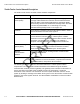
Tools and Supplies Needed for Installation TT210 Installation Planning Tools and Supplies Needed for Installation The following tools and supplies are recommended for performing installations.
5 Installing the TT210 Terminal on Dry Vans Introduction This chapter describes how to install the terminal on Dry Vans. AF T Topics in this chapter include: Terminal with 7-way Power . . . . . . . . . . . . . . . . . . . . . . . . . . . . . . . . . . . . . . . . . . . 5-2 If you have technical questions, please contact Qualcomm Enterprise Services (QES) Customer Support.
Terminal with 7-way Power Installing the TT210 Terminal on Dry Vans Terminal with 7-way Power Overview The TT210 terminal installs outside the trailer on the trailer nose just below (approximately 1/2") the top rail horizontal rivet line where the trailer skin attaches to the top rail, preferably in the 7-way receptacle vertical bay. Ensure the terminal clears the trailer’s top rail internally and externally, being aware that the top rail may extend below the rivet line.
Installing the TT210 Terminal on Dry Vans Installation • Cargo Sensor. The cargo sensor determines whether the trailer is empty or not empty. It is installed inside the trailer near the top of the nose of the trailer. It is necessary to cut a 9.5" x 12" hole in the trailer nose plywood liner to provide the cargo sensor with an unobstructed view of the inside of the trailer. Typically, it is mounted in the bay next to the terminal. Determine which mount to use.
Installation Installing the TT210 Terminal on Dry Vans The following illustration shows typical wiring for a dry van.
Installing the TT210 Terminal on Dry Vans Position a portable scaffold in front of the trailer nose where the terminal will be installed. 4. 5. 80-J7615-1 Rev. A 04AAA_131 Carefully ascend the scaffolding to where the terminal will be installed and place it as high up as is practical between the vertical support rails in the 7-way bay. Make sure it’s at least .50 inch from the top rivet line. D 3. R AF T 2. Installation Mark the position of the 7/8” hole for the cable then drill both holes.
Installation Installing the TT210 Terminal on Dry Vans drawing showing white markings on top of connector.?? 11. Remove the 7-way receptacle cover from outside the trailer. 12. Drill a 7/8" hole for the 7-way cable in or by the 7-way. 13. Run the 7-way cable from the 7/8” hole at the TT210 down to the 7-way hole. 5-6 D R AF T 10. a. Fish the cable down to the 7-way from the terminal using a fish tape from below or a hook wire at the 7-way. b.
Installing the TT210 Terminal on Dry Vans c. Installation Install the supplied split grommet on the cable going to the TT210 terminal where the cable passes through the trailer skin. Dry Van AF T System Power/Accessory Cable routed from the mount to the 7-way connector R 10AAA_08 Note 14. D When installed on a plate nose trailer, the TT210 system power/accessory cable routes externally down the outside nose of the trailer. Make wire connections at the 7-way receptacle.
Installation Installing the TT210 Terminal on Dry Vans b. Connect the white GROUND wire to pin 1 in the 7-way receptacle using a ring terminal. 3 amp Fuse Blue (PWR) Pin 7 White (GND) Pin 1 BLU BL K BRN GR YEL N RED 05AAA_217E 5-8 Mount the unit in the 7-way bay using the six rivets. These should be installed top, top, middle, middle, bottom, bottom. Remove battery/connector cover using a #1 Phillips screwdriver. b.
Installing the TT210 Terminal on Dry Vans Installation Place the battery into place, use provided zip ties, attach the battery connector, and install the battery cover with provided screws. Only use hand tools when tightening the phillips head screws on the battery cover. Battery Cover Connector 10AAA_09B D R AF T Battery Pack 80-J7615-1 Rev. A MAY CONTAIN U.S.
Installation Installing the TT210 Terminal on Dry Vans Battery Pack 23. 5-10 Close the terminal and make sure it is sealed. a. Ensure gasket is properly seated. b. Attach the unit cover. Configure or pair the terminal to the proper trailer ID. R 22. 10AAA_027A a. Wake up the terminal with the key fob or 7-way power. b. Using the configuration tool, go into the configure screen and enter the trailer ID. D 21. AF T Battery Compartment Open Perform system verification.
6 Installing the TT210 Terminal on Plate Nose Trailers Introduction This chapter describes how to install the terminal on Plate Nose Trailers. AF T Topics in this chapter include: Terminal with 7-way Power . . . . . . . . . . . . . . . . . . . . . . . . . . . . . . . . . . . . . . . . . . . 6-2 If you have technical questions, please contact Qualcomm Enterprise Services (QES) Customer Support.
Terminal with 7-way Power Installing the TT210 Terminal on Plate Nose Trailers Terminal with 7-way Power Overview The TT210 terminal installs outside the trailer on the trailer nose just below (approximately 1/2") the top rail horizontal rivet line where the trailer skin attaches to the top rail, preferably in the 7-way receptacle vertical bay. Ensure the terminal clears the trailer’s top rail internally and externally, being aware that the top rail may extend below the rivet line.
Installing the TT210 Terminal on Plate Nose Trailers Installation unobstructed view of the inside of the trailer. Typically, it is mounted in the bay next to the terminal. Determine which mount to use. Refer to Chapter 10: Installing the Cargo Sensor. - If you have 3" from the inside skin to the outside liner, use a flat internal mount. - If you have at least 2" but less than 3" from the skin to the outside liner, use a 1" pan. - if container or plate nose use the 3" pan • Door Sensor.
Installation Installing the TT210 Terminal on Plate Nose Trailers Position a portable scaffold in front of the trailer nose where the terminal will be installed. 04AAA_131 D R AF T 2. 6-4 MAY CONTAIN U.S. AND INTERNATIONAL EXPORT CONTROLLED INFORMATION 80-J7615-1 Rev.
Installing the TT210 Terminal on Plate Nose Trailers Carefully ascend the scaffolding to where the terminal will be installed and place it as high up as is practical between the vertical support rails in the 7-way bay. Make sure it’s at least .50 inch from the top rivet line. D R AF T 3. Installation 4. 5. 80-J7615-1 Rev. A Mount the unit in the 7-way bay using the six rivets. These should be installed top, top, middle, middle, bottom, bottom. a. Drill a 3/16" hole then attach the first rivet.
Installation Installing the TT210 Terminal on Plate Nose Trailers 6. Drill a 7/8" hole for the 7-way power cable at the rear of the battery compartment being careful not to damage the plastic case around the hole. 7. Drill a 7/8" hole for the 7-way cable in or by the 7-way. 8. Run the 7-way cable. Typically, this is from the hole at the TT210 down to the 7-way hole. a. Fish the cable down to the 7-way from the terminal using a fish tape from below or a hook wire at the 7-way. b.
Installing the TT210 Terminal on Plate Nose Trailers b. Installation Connect the white GROUND wire to pin 1 in the 7-way receptacle using a ring terminal. 3 amp Fuse Blue (PWR) Pin 7 White (GND) Pin 1 BLU BL K BRN GR YEL N RED 05AAA_217E AF T If the 7-way receptacle has circuit breakers, be sure to connect on the unprotected (truck) side of the circuit breakers. Connect the circular connector to the terminal. This connector is “keyed” and will only go on in one position.
Installation Installing the TT210 Terminal on Plate Nose Trailers Battery Cover Battery Pack AF T Connector D R 10AAA_09B Battery Pack Battery Compartment Open 10AAA_027A 6-8 MAY CONTAIN U.S. AND INTERNATIONAL EXPORT CONTROLLED INFORMATION 80-J7615-1 Rev.
Installing the TT210 Terminal on Plate Nose Trailers 15. 16. Configure or pair the terminal to the proper trailer ID. a. Wake up the terminal with the key fob or 7-way power. b. Using the configuration tool, go into the configure screen and enter the trailer ID. Close the terminal and make sure it is sealed. a. Ensure gasket is properly seated. b. Attach the unit cover. Perform system verification. See Chapter 14: Performing System Verification. D R AF T 17. Installation 80-J7615-1 Rev.
Installing the TT210 Terminal on Plate Nose Trailers D R AF T Installation 6-10 MAY CONTAIN U.S. AND INTERNATIONAL EXPORT CONTROLLED INFORMATION 80-J7615-1 Rev.
7 Installing the TT210 Terminal on Containers Introduction This chapter describes how to install the dryvan terminal. AF T Topics in this chapter include: Overview . . . . . . . . . . . . . . . . . . . . . . . . . . . . . . . . . . . . . . . . . . . . . . . . . . . . . . . . . 7-2 Types of Containers . . . . . . . . . . . . . . . . . . . . . . . . . . . . . . . . . . . . . . . . . . . . . . . . . 7-3 Installation . . . . . . . . . . . . . . . . . . . . . . . . . . . . . . . . . . . . . . . . . . . . . . .
Overview Installing the TT210 Terminal on Containers Overview The TT210 terminal installs outside the container on the container nose just below (approximately 1/2") the top rail horizontal rivet line where the container skin attaches to the top rail. Ensure the terminal clears the container’s top rail internally and externally, being aware that the top rail may extend below the rivet line. The unit should be positioned as high as possible on the driver’s side of center.
Installing the TT210 Terminal on Containers Planning for Optional Cargo Sensor Planning for Optional Cargo Sensor Before starting the installation, consider if the optional cargo sensor will be installed. Determining if a sensor will be used before beginning the installation, results in better planning and preparation. The cargo sensor determines whether the container is empty or not empty. It is necessary to cut a 9.5" x 12" hole in the container nose plywood when a cargo sensor is used.
Installation Installing the TT210 Terminal on Containers • CIMC Cargo Sensor TT210 Sensor Cable AF T Depending on what type of container you have, the installation may be slightly different. Installation On the outside of the container, locate where the TT210 terminal will be installed. 2. Position a portable scaffold in front of the container nose where the terminal will be installed. D R 1. 04AAA 131 7-4 MAY CONTAIN U.S. AND INTERNATIONAL EXPORT CONTROLLED INFORMATION 80-J7615-1 Rev.
Installing the TT210 Terminal on Containers Carefully ascend the scaffolding to where the terminal will be installed and place it as high up as is practical between the vertical support rails in the 7-way bay. Make sure it’s at least .50 inch from the top. 4. 80-J7615-1 Rev. A D R AF T 3. Installation Mount the unit on the driver side of center using the six rivets. These should be installed top, top, middle, middle, bottom, bottom. a. Drill a 3/16” hole then attach the first rivet. b.
Installation Installing the TT210 Terminal on Containers NEED FIGURE> KEVIN TO GET JERRY DRAWING INFO...gromits etc. 7. Verify all mechanical and electrical components (cables, wires, optional sensors) are properly connected. 8. Install the cargo sensor (follow directions in Chapter 10: Installing the Cargo Sensor) 9. Install the battery inside the terminal. Place the battery into place, use provided zip ties, connect the connector, and install the battery cover with provided screws.
Installing the TT210 Terminal on Containers Perform system verification. See Chapter 14: Performing System Verification. D R AF T 12. Installation 80-J7615-1 Rev. A MAY CONTAIN U.S.
Installing the TT210 Terminal on Containers D R AF T Installation 7-8 MAY CONTAIN U.S. AND INTERNATIONAL EXPORT CONTROLLED INFORMATION 80-J7615-1 Rev.
8 Installing the TT210 Terminal on Reefers Introduction This chapter provides guidelines and instructions for installing the TT210 on a refrigerated trailer. AF T Topics in this chapter include: Reefer Minimum Requirements . . . . . . . . . . . . . . . . . . . . . . . . . . . . . . . . . . . . . . . . 8-2 TT210 Input Power Options for Refrigerated Trailers . . . . . . . . . . . . . . . . . . . . . . . 8-5 Cable and Wiring Schematic . . . . . . . . . . . . . . . . . . . . . . . . . . . . . . . . . . . . .
Reefer Minimum Requirements Installing the TT210 Terminal on Reefers Reefer Minimum Requirements Tethered and Untethered System Comparison Unlike the tethered system, the untethered system currently does not transfer reefer data to the MCP unit in the tractor. However, it does send trailer ID so that connects and disconnects can be detected by the MCP unit in the tractor.
Installing the TT210 Terminal on Reefers Software Software Make sure you have the correct software for the appropriate reefer model. Carrier Advance Controller units must have DataTrak software 04.03.00 or higher installed and SATCOM configured to “Other.” To check the software version, follow these steps. 1. Turn ON power. 2. Wait for self-test to finish. 3. Press SELECT until VIEW DATA displays. 4. Press the DOWN ARROW to view the data list items. Choose INSTALLED OPTIONS.
Software Installing the TT210 Terminal on Reefers 9. Turn ON the reefer power switch. 10. Wait for unit to go to CONFIGURATION MODE. 11. Press = (equal key). 12. Press the DOWN ARROW to view hidden menu. Check that SATCOM is set to “other.” Note The Carrier “Qualcomm” setting is for tethered system units.
Installing the TT210 Terminal on Reefers TT210 Input Power Options for Refrigerated Trailers Carrier Standard Controller units must have an EEPROM chip loaded with the DataTRAK software version 3.30 or higher. To check the software version, follow these steps. 1. Turn ON power. 2. Wait for self-test to finish. 3. Press UNIT DATA. 4. Press the DOWN ARROW until the software version displays. 5. If the software version is not 3.30 or higher, change the EEPROM.
Cable and Wiring Schematic Installing the TT210 Terminal on Reefers Cable and Wiring Schematic Supplied Fuse Holder Terminal Connector Door/Aux Wires D R AF T Reefer Data/Power Connector 8-6 MAY CONTAIN U.S. AND INTERNATIONAL EXPORT CONTROLLED INFORMATION 80-J7615-1 Rev.
Installing the TT210 Terminal on Reefers Mount Overview Mount Overview The TT210 reefer mount attaches to the top rail of the trailer. The TT210 power/accessory cable runs from the TT210 terminal to the 7-way receptacle. Thoroughly evaluate the trailer area where the mount will be located to determine if the T2 system can be installed on the trailer. The trailer should be free of extensive damage in all installation areas.
Mount Installation 1. Installing the TT210 Terminal on Reefers On the outside of the trailer, locate an appropriate area in the top channel where the TT210 reefer mount will be installed. Make sure it’s away from any sources of heat (muffler, exhaust air, etc.) Note: Avoid installing the TT210 mount near air and/or electrical lines.
Installing the TT210 Terminal on Reefers Mount Installation 4. Attach the Hirose connector to the terminal. 5. Where the cable enters the terminal, install the provided split grommet securely into the cable hole. Ensure the grommet is fully seated. 6. Route the TT210 power/accessory cable from the mount to the inside of the reefer on the left (driver) side towards the 7-way receptacle. 7.
Making Power and Signal Connections for Carrier Units Installing the TT210 Terminal on Reefers Making Power and Signal Connections for Carrier Units HEAT COOL DEFROST ALARM START- STOP CONTINUO US SETPOINT BOX TEMPER ATURE = MANUAL DEFROST START / RUN ALARM LIST START-STOP/ CONTINUOUS ! SELECT o OFF NOTE: This is the only 3-pin connector located in the area.
Installing the TT210 Terminal on Reefers a. Making Power and Signal Connections for Carrier Units For newer model Carrier units, use cable # 45-J7856-6 with the 3-pin Packard connector. For older model Carrier units or units with Data Loggers, use cable # 45-J7854-6 with the 5-pin circular Deutsch connector. D R b. AF T 07AAA_097 07AAA_102 5. Connect the reefer power (ORN) wire with the SPK7 (switched power) wire.
Making Power and Signal Connections for Carrier Units 8. Installing the TT210 Terminal on Reefers Secure the TT210 power/accessory cable and the reefer cable along the respective routes using P clamps. Ensure the cables are held firmly in place.
Installing the TT210 Terminal on Reefers System Verification and Final Steps For pre-2010 Thermo King reefers, use cable # 45-J7857-6. For 2010 or newer, use cable # 45-JB082-6. 9. Route the reefer data cable so it is secure to prevent it from being damaged. 10. Connect the TT210 battery to the mating TT210 battery connector. 11. Connect to the TT210 unit with the 6-pin square Deutsch connector on the reefer interface cable. 12.
System Verification and Final Steps Installing the TT210 Terminal on Reefers Verify the lower cover seal is in place and not damaged. figure showing back and gasket??? 3. Reinstall the lower cover being careful not to over-tighten. 4. If you are using a battery-powered drill, the drill should NOT be set on “Drill.” The drill should be set on a low torque setting. D R AF T 2. 8-14 MAY CONTAIN U.S. AND INTERNATIONAL EXPORT CONTROLLED INFORMATION 80-J7615-1 Rev.
9 Retrofitting for TT210 Introduction This chapter describes installation procedures if you are moving from a TT200 to a TT210. AF T Topics in this chapter include: Retrofit steps . . . . . . . . . . . . . . . . . . . . . . . . . . . . . . . . . . . . . . . . . . . . . . . . . . . . . . 9-3 If you have technical questions, please contact Qualcomm Enterprise Services (QES) Customer Support.
Retrofit Kit Retrofitting for TT210 Retrofit Kit 65-J7584-3 Master Pack, Retrofit, TT210 which includes: • TT210 terminal • Auxiliary Battery pack • 65-J7565-2 Cable: TT210 to TT200 wiring adapter cable kit • 65-J7588-1 Retrofit Kit which contains - 50-J7594-1 Cover Plate, Retrofit, Terminal Mount - 50-J4883-1 Gasket • 65-J7601-1 Rivet Kit, TT210 Mtg, XTRA (MGLP-U6-E STEEL) D R AF T • 9-2 MAY CONTAIN U.S. AND INTERNATIONAL EXPORT CONTROLLED INFORMATION 80-J7615-1 Rev.
Retrofitting for TT210 Retrofit steps Retrofit steps Remove the TT200 1. Remove the 24 nuts holding the pan on the trailer. Save the nuts for installing the TT210. 2. Pull the TT210 pan off leaving the terminal and battery attached to the pan. 3. Disconnect the cables from the TT200 unit. Cut the zip ties. • Remove the 20-pin connector from the bottom of the TT200 unit. • Remove both antenna connectors from the TT200 unit. • Remove the TT200 battery connector.
Connect the TT210 3. Retrofitting for TT210 Replace the existing gasket with a new one. Connect the TT210 Remove the battery cover from the TT210. 2. Feed the Hirose connector through the 7/8” hole and connect to the terminal. 3. Install the 7/8” split grommet around the cable in the plate. 4. Spool the remaining cable at the back of the plate and use zip ties to hold in place. 5. Install the TT210 retrofit plate over the existing studs in the trailer and attach the 24 nuts. 6.
10 Installing the Cargo Sensor Introduction This chapter provides general information about the TT210 system optional cargo sensor. AF T Topics in this chapter include: TT210 System Cargo Sensor Overview. . . . . . . . . . . . . . . . . . . . . . . . . . . . . . . . . 10-2 Installing the Cargo Sensor Using 3" or 1" Pan Mount . . . . . . . . . . . . . . . . . . . . . 10-3 Installing the Cargo Sensor Using a Flat Internal Mount- . . . . . . . . . . . . . . . . . . .
TT210 System Cargo Sensor Overview Installing the Cargo Sensor TT210 System Cargo Sensor Overview AF T The cargo sensor determines the status of a trailer’s cargo load (either empty, loading, or loaded) and provides this information when queried. The cargo sensor cable assembly is part of the TT210 system power/accessory cable assembly.
Installing the Cargo Sensor Installing the Cargo Sensor Using 3" or 1" Pan Mount There are three different options for mounting the cargo sensor: two using external pans and one using a flat internal mount. Both external pan mounts have the same basic installation steps. • If you have a plate nose trailer or container or a dry van with less than 2", you will need to use a 3" pan mount. See Installing the Cargo Sensor Using 3" or 1" Pan Mount on page 10-3.
Installing the Cargo Sensor Using 3" or 1" Pan Mount Position a portable scaffold in front of the trailer nose where the cargo sensor will be installed. AF T 1. Installing the Cargo Sensor 04AAA_131 Carefully ascend the scaffolding. R 2. Note 3. 10-4 D Mount on the bay next to the TT210 terminal which will be on the driver’s side (left of center) no closer than 18" to the trailer sidewall. Locate the mounting position of the cargo sensor.
Installing the Cargo Sensor Place the cargo mount installation template as high up as practical between the vertical support rails. AF T 4. Installing the Cargo Sensor Using 3" or 1" Pan Mount 10AAA_02 Secure the template with two self-drilling screws through holes in the handle. 6. Using the template as a guide, drill the 18 stud holes using a 3/8" drill. 7. Trace the inside of the template using a felt-tip pen. D R 5. Trace the inside of the template 10AAA_04 8. 80-J7615-1 Rev.
Installing the Cargo Sensor Using 3" or 1" Pan Mount 9. 10. Installing the Cargo Sensor Remove the self-drilling screws and the template. Drill a 7/8" hole on each of the four corners of the template using the pilot holes as a guide. Drill four 7/8" corner holes AF T Scribed Line Completely cut out the marked area for the cargo sensor with a cutting tool, being careful not to drop the newly cut panel inside or outside of the trailer. Avoid sharp edges and debur if necessary. 12.
Installing the Cargo Sensor 14. Installing the Cargo Sensor Using 3" or 1" Pan Mount Remove the protective plastic cover from the double-sided adhesive tape on each of the four prefabricated stud plates. Stud Plate Double-sided Tape Stud Plate Stud Plate Double-sided Tape Stud Plate 04AAA _135A Each of the four stud plates are installed on the inside of the trailer skin. Position each to line up with the stud holes that were just drilled.
Installing the Cargo Sensor Using 3" or 1" Pan Mount Mount the cargo sensor to the 3" or 1"cargo sensor pan mount using four lock nuts and four flat washers. Tighten just until snug and torque to 20 inch-pounds +/- 5 inchpounds. AF T 17. Installing the Cargo Sensor 10AAA_010A 19. 10-8 For a container or plate nose: Place the grommet around the cargo sensor connector and down the cable about 9". b. Route the cable through the 7/8" hole in the bottom of the 3" pan and connect to the sensor. c.
Installing the Cargo Sensor Installing the Cargo Sensor Using a Flat Internal Mount Dry Van Use 3" or 1" Pan Internal Wiring Plate Nose and Containers Use 3" Pan External Wiring Plate Nose AF T Container R Installing the Cargo Sensor Using a Flat Internal Mount Note 1. 2. 80-J7615-1 Rev. A D Mount on the bay next to the TT210 terminal which will be on the driver’s side (left of center) no closer than 18" to the trailer sidewall. Locate the mounting position of the cargo sensor.
Installing the Cargo Sensor Using a Flat Internal Mount 3. Installing the Cargo Sensor Center the cargo sensor side to side in the hole. The bottom edge of the plywood hole should be a minimum of 6" below the lower lip of the cargo sensor cone. Trailer Exterior Cut Interior Plywood for Cargo sensor AF T Cargo Sensor Mount Riveted to Trailer skin 10AAA_48 Trailer Skin From the inside of the trailer, while holding the mount in place, drill four 3/16" rivet holes.
Installing the Cargo Sensor 6. Installing the Cargo Sensor Using a Flat Internal Mount Attach the cargo sensor to the cargo sensor mount using the supplied hardware. Tighten just until snug and torque to 20 inch-pounds +/- 5 inch-pounds. Interior view AF T Exterior Mounted Terminal Dual Cargo Sensor 10AAA_21A1 Route and connect the cargo sensor cable. Ensure that the cable does not block the cargo sensor or is visible in the cone area. Secure cable. D 7. R Interior Plywood 80-J7615-1 Rev.
TT210 System Cargo Sensor Validation Installing the Cargo Sensor TT210 System Cargo Sensor Validation The TT210 system terminal’s cargo sensor default setting will “wake up” the cargo sensor every 30 minutes and check for a cargo load. This is customer configurable. The terminal can be customer configured to: • Message immediately • Send on next report • Respond to a ping • Ignore An ultrasonic sensor detects objects approximately 20 feet back from the nose of the trailer.