
User's Guide


Installation & User Guide
DGA-LT1 site items to be confirmed:
• Adequate location with proper clearance for mounting the DGA-LT1 monitor has been
identified
o The system is optimized for transformers that are oil-filled.
o The recommended installation point for the DGA-LT1 is the transformer oil drain valve
o Qualitrol requires a 1” NPT for the transformer oil supply valve. A DGA-LT1
configured with a 2” to 1” reducing adapter is available to order
o A 5” (12.7cm) clearance in the z direction is required for adequate spacing. If an
adapter is required, a 6” (15.3 cm) z direction clearance is required.
o A minimum of a 3.5” (8.9 cm) radial (x or y direction) clearance between the valve
centerline and any surrounding structure, including the transformer foundation, is
required for proper installation clearance space. There also must be adequate space
to use a 12” (~30 cm long) wrench to tighten DGALT1 onto the drain valve.
• Qualitrol recommends a Dissolved Gas Analysis sample be taken at or immediately prior to
installation to provide a baseline level for Hydrogen concentration
• To prevent atmospheric air from entering the transformer, the DGA-LT1 requires positive oil
pressure at the drain valve for installation. The DGA-LT1 should not be installed if the
equipment is under vacuum conditions.
Transformer Selection
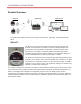
The QualConnex system uses cellular connection to transmit data from the QGateway to the cloud. To achieve
this, there must be adequate cellular signal present where the QGateway is installed to allow for reliable
transmission of data.
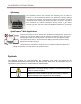
Transformer Configuration
The transmission distance from the DGA-LT1 to the QGateway is strongly impacted by obstructions. This
includes whether the DGA-LT1 is to be located in an enclosed transformer cabinet or in the open air when
installed. Take note of the type of transformer and the location of the drain valve (or other approved installation
point for the DGA-LT1 sensor) to properly determine the maximum distance allowed between each DGA-LT1
and QGateway. The location of the drain valve (N, S, E, W, etc.) is also critical to signal range and must be
noted. See the stated Typical RF Range listed in the QGateway Specification section.
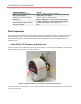
Transformer Distance Evaluation
The distance between each identified transformer for evaluation should be known. This will confirm the
QGateway range to DGA-LT1 and scale the number of QGateway to sensors required. This step can be done
using a web-based tool, like Google Earth, to approximate the distance or can be performed with site surveying
or site maps as available. Google Earth, at time of writing, includes a measurement tool that may be used for
distance measurements.