HPC-1000 10.
Contact Info: Quanmax Inc. 5F, No. 415, Ti-Ding Blvd. Sec. 2, NeiHu District, Taipei, Taiwan 114 Tel: +886-2-2799-2789 Fax: +886-2-2799-7399 Visit our site at: www.quanmax.com © 2009 Quanmax Inc. All rights reserved. The information in this user’s guide is provided for reference only. Quanmax does not assume any liability arising out of the application or use of the information or products described herein.
Content Content Content....................................................................................................................... 3 Figures ....................................................................................................................... 4 Tables......................................................................................................................... 5 Safety Instructions.......................................................................................
Figures Figures Figure 1 Mechanical Layout - Front and Side ............................................ 16 Figure 2 Mechanical Layout - I/O Panel..................................................... 16 Figure 3 Mechanical Dimensions ............................................................... 19 Figure 4 Turning on the system.................................................................. 20 Figure 5 Mounting hole locations on the HPC-1000...................................
Tables Tables Table 1 Specifications ................................................................................ 15 Table 2 USB (USB2.0 Port 0, 1 Type A Connector).................................... 17 Table 3 LAN (10/100/1000 Ethernet RJ-45 Connector).............................. 17 Table 4 Digital I/Os (DB9 Female Connector) ............................................ 17 Table 5 COM1 (RS-232/422/485 DB-9 Connector) ....................................
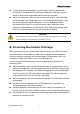
Safety Instructions Safety Instructions Before You Begin Before handling the product, read the instructions and safety guidelines on the following pages to prevent damage to the product and to ensure your own personal safety. Refer to the “Advisories” section in the Preface for advisory conventions used in this user’s guide, including the distinction between Warnings, Cautions, Important Notes, and Notes. Always use caution when handling/operating a computer.
Safety Instructions To help avoid possible damage to system boards, wait five seconds after turning off the computer before removing a component, removing a system board, or disconnecting a peripheral device from the computer. When you disconnect a cable, pull on its connector or on its strain-relief loop, not on the cable itself. Some cables have a connector with locking tabs. If you are disconnecting this type of cable, press in on the locking tabs before disconnecting the cable.
Safety Instructions Instructions for Lithium Battery WARNING Danger of explosion when battery is replaced with incorrect type. Only replace with the same or equivalent type recommended by the manufacturer. Do not dispose of lithium batteries in domestic waste. Dispose of the battery according to the local regulations dealing with the disposal of these special materials (e.g.
Preface Preface How to Use This Guide This guide is designed to be used as step-by-step instructions for installation, and as a reference for operation, troubleshooting, and upgrades. NOTE Driver downloads and additional information are available under Downloads on our web site: www.quanmax.com. Unpacking When unpacking, follow these steps: 1. 2. 3. After opening the box, save it and the packing material for possible future shipment. Remove all items from the box.
Preface interference will not occur in a particular installation. If this equipment does cause interference to radio or television equipment reception, which can be determined by turning the equipment off and on, the user is encouraged to try to correct the interference by one or more of the following measures: Reorient or relocate the receiving antenna. Increase the separation between the equipment and receiver.
Preface login to obtain a Return Material Authorization (RMA) Number. If you do not have an account, send an email to support@quanmax.com to apply for one. All product(s) returned to Quanmax for service or credit must be accompanied by a Return Material Authorization (RMA) Number. Freight on all returned items must be prepaid by the customer who is responsible for any loss or damage caused by common carrier in transit.
Preface two-hour warm-up period to bring it up to normal operating temperature before turning it on. Failure to do so may cause damage to internal components, particularly the hard disk drive. Humidity High-humidity can cause moisture to enter and accumulate in the system. This moisture can cause corrosion of internal components and degrade such properties as electrical resistance and thermal conductivity.
Preface Line conditioners go beyond the over voltage protection of surge protectors. Line conditioners keep a system’s AC power source voltage at a fairly constant level and, therefore, can handle brownouts. Because of this added protection, line conditioners cost more than surge protectors. However, line conditioners cannot protect against a complete loss of power.
Chapter 1 Chapter 1 Introduction Overview The HPC-1000 10.1” Panel PCs is combining the latest Intel 45nm Intel® Atom™ processor with the high integration of the Intel® 945GSE/ ICH7-M chipset for a wide range of industrial applications. Storage includes a 2.5" SATA hard drive or a solid-state drive (SSD), and Compact Flash. Supported interfaces include a GbE LAN, 2x serial ports, USB 2.0 ports, DVI-I, thus easily meeting a broad range of customer requirements.
Chapter 1 Product Specifications System CPU Chipset Memory Internal Storage Expansion slots Cooling Material I/Os LCD Display Display type & size Brightness Resolution Touch Screen Network RFID Audio Camera Environmental Specification Temperature Shock Vibration Intel® Atom™ Processor N270 Intel® 945GSE/ICH7-M 1x DDR2 400/533 SO-DIMM Socket, up to 2GB 1x 2.5” SATA HDD or 1x SSD 1x CompactFlash None Fan-less Plastic front bezel & SECC chassis 1x GbE, RJ-45 4x USB 2.
Chapter 1 System Tour Front and Side Panel Figure 1 Mechanical Layout - Front and Side Rear and I/O Panel Figure 2 Mechanical Layout - I/O Panel HPC-1000 User’s Manual 16
Chapter 1 WARNING Be sure not to block any air vents on the computer. Blocked air vents can cause thermal problems. External Connectors Table 2 USB (USB2.
Chapter 1 Table 6 KB/MS (PS/2 KB/MS Mini-DIN Connector) Pin 1 2 3 4 5 6 Signal KBDAT MSDAT GND +5V KBCLK MSCLK Table 7 DVI-I (DVI-I Connector) Pin 1 3 5 7 9 11 13 15 17 19 21 23 PIN C1 C2 C3 C4 C5 HPC-1000 User’s Manual Signal Name Pin Signal Name TX2N 2 TX2P GND 4 TX5N TX5P 6 SD_CLK SD_DATA 8 VSYNC TX1N 10 TX1P GND 12 TX4N TX4P 14 VGA_PWR VGA_EN 16 HPD TX0N 18 TX0P GND 20 TX6N TX6P 22 GND TCLP 24 TXLN Signal Name Analog red Analog green Analog blue Analog horizontal sync Analog ground 18
Chapter 1 Mechanical Dimensions Figure 3 Mechanical Dimensions HPC-1000 User’s Manual 19
Chapter 2 Chapter 2 Getting Started Power Connection Turning on the system 1. 2. 3. 4. Secure the power adapter cable to the DC jack (DC IN) of the HPC-1000 Connect the power cable to the power adapter Connect the power cable to a power outlet Press the power switch on the front panel to turn on the system Figure 4 Turning on the system VESA Mounting The HPC-1000 comes with VESA FDMI 75 standard mounting holes as shown below. Use 4 screws with the appropriate length for your VESA mounting bracket.
Chapter 2 Wall Mount Kit . Below are the demonstrations of how to use Quanmax wall-mount kits Step1 Secure the VESA kit to the panel PC using the 4 screws. (M4x5L flat head) Step2 Install the wall-mount kit to the proper place of the wall by using the 6 screws. Step3 Attach the panel PC to the wall-mount kit which has been well fixed on the wall.
Chapter 2 Desktop Stand Step1 Assembling the desktop stand Step2 Secure the VESA kit to the desktop stand using the 4 screws. (M4x5L round head) Step3 Secure the panel PC to the desktop stand using the 4 screws. (M4x5L flat head) Figure 7 Install Desktop Stand Operating System and Drivers If your product does not come with an operating system pre-installed, you will need to install an operating system and the necessary drivers to operate it.
Chapter 2 NOTE 1. To install the VGA driver, please double-click “Setup.exe” which is under below folder. \Intel VGA\Utilities 2. If your system goes into suspend mode, please push the power button for 2 seconds to wake up the system. Maintenance and Prevention Your HPC-1000 system requires minimal maintenance and care to keep it operating correctly. Occasionally wipe the system with a soft dry cloth.