KEMF-4010 FlexATX Embedded Motherboard with AMD Athlon™ Single and Dual-Core Processors and AMD® 780E + SB710 chipset User’s Guide KEMF-4010 User’s I
Contact Info: Quanmax Inc. 5F, No. 415, Ti-Ding Blvd. Sec. 2, NeiHu District, Taipei, Taiwan 114 Tel: +886-2-2799-2789 Fax: +886-2-2799-7399 Visit our site at: www.quanmax.com © 2009 Quanmax Inc. All rights reserved. The information in this user’s guide is provided for reference only. Quanmax does not assume any liability arising out of the application or use of the information or products described herein.
Content Content Content ...................................................................................................................... 3 Figures ....................................................................................................................... 5 Tables ......................................................................................................................... 6 Safety Instructions .....................................................................................
Content Chapter 4 AMI BIOS Setup .................................................................................... 41 Overview ................................................................................................ 41 Main Menu.............................................................................................. 42 Advanced Menu ..................................................................................... 43 Boot Menu .............................................................
Figures Figures Figure 1 Block Diagram ............................................................................................ 16 Figure 2 KEMF-4010 Mechanical Dimensions ......................................................... 17 Figure 3 Jumper Connector...................................................................................... 18 Figure 4 KEMF-4010 Jumper and Connector Locations .......................................... 19 Figure 5 CPU alignment in Socket AM2 ..........................
Tables Tables Table 1 KEMF-4010 Specification ................................... Table 2 Jumper List ............................................. Table 3 JP1, JP2, JP3, JP6, JP7, JP13, COM Port Signal / Power Selection .... Table 4 JP4, DIO Signal / Power Selection ............................ Table 5 JP5, Parallel Port Signal Selection ............................ Table 6 JP8, ATX/AT mode Selection ................................ Table 7 JP9, Clear CMOS Selection .................................
Tables Table 35 PCI1, 32-bit / 33Mhz / 5V-key PCI Slot ........................ Table 36 PCIE1, Standard PCI Express x16 Slot ........................ Table 37 USB1, USB2, USB2.0 Pin Header ............................ Table 38 LPT1, Parallel Port DB-25 Connector ......................... Table 39 PCIE2, PCIE3, Standard PCI Express x1 Slot ................... Table 40 SATAII_1, SATAII_2, SATAII_3, SATAII_4 ,SATAII_5 ,SATAII_6 ....... Table 41 MPCIE1, Mini PCIe Connector ..............................
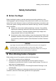
Safety Instructions Safety Instructions Before You Begin Before handling the product, read the instructions and safety guidelines on the following pages to prevent damage to the product and to ensure your own personal safety. Refer to the “Advisories” section in the Preface for advisory conventions used in this user’s guide, including the distinction between Warnings, Cautions, Important Notes, and Notes. Always use caution when handling/operating a computer.
Safety Instructions To help avoid possible damage to system boards, wait five seconds after turning off the computer before removing a component, removing a system board, or disconnecting a peripheral device from the computer. When you disconnect a cable, pull on its connector or on its strain-relief loop, not on the cable itself. Some cables have a connector with locking tabs. If you are disconnecting this type of cable, press in on the locking tabs before disconnecting the cable.
Preface Preface How to Use This Guide This guide is designed to be used as step-by-step instructions for installation, and as a reference for operation, troubleshooting, and upgrades. NOTE Driver downloads and additional information are available under Downloads on our web site: www.quanmax.com. Unpacking When unpacking, follow these steps: 1. After opening the box, save it and the packing material for possible future shipment. 2. Remove all items from the box.
Preface their own expense. Changes or modifications not expressly approved by Quanmax could void the user's authority to operate the equipment. NOTE The assembler of a personal computer system may be required to test the system and/or make necessary modifications if a system is found to cause harmful interference or to be noncompliant with the appropriate standards for its intended use. Warranty Policy Limited Warranty Quanmax Inc.’s detailed Limited Warranty policy can be found under Support at www.
Preface and building replacement products. If Quanmax repairs or replaces a product, its warranty term is not extended. Shipments not in compliance with this Limited Warranty Return Policy will not be accepted by Quanmax.
Preface Altitude Operating a system at a high altitude (low pressure) reduces the efficiency of the cooling fans to cool the system. This can cause electrical problems related to arcing and corona effects. This condition can also cause sealed components with internal pressure, such as electrolytic capacitors, to fail or perform at reduced efficiency.
Chapter 1 Chapter 1 Introduction Overview The KEMF-4010 is a FlexATX embedded motherboard that built with the fastest onboard graphics - AMD® 780E and supporting AMD Athlon™ X2 dual-core processor and DDR2 DIMM up to 8GB. This embedded board offers the latest video performance and I/O interfaces at an extremely attractive price/performance ratio and measures 229 x 191mm, a 42 percent space reduction over ATX boards.
Chapter 1 Product Specifications CPU Support AMD Athlon™ Single and Dual-Core Processors Chipset AMD780E + SB710 Memory 2x DDR2 400/533/667/800 DIMM Socket, up to 8GB BIOS AMI PnP 8MbFlash Display Integrated ATI Radeon™ HD 3200 graphics Dual Independent Display Support Single/ Dual channel 18/24 bit LVDS, with a optional LVDS to DVI-D cable 1x HDMI 1x VGA LAN 3x RJ-45, Gigabit Ethernet (Realtek 8111C) Audio Peripheral Support Realtek HD audio codec onboard 2W Amplifier support One audio sta
Chapter 1 System Block Diagram Figure 1 Block Diagram KEMF-4010 User’s 16
Chapter 1 Mechanical Dimensions Figure 2 KEMF-4010 Mechanical Dimensions KEMF-4010 User’s 17
Chapter 2 Chapter 2 Hardware Settings Overview This chapter provides the definitions and locations of jumpers, headers, and connectors. Jumpers The product has several jumpers which must be properly configured to ensure correct operation. Figure 3 Jumper Connector For a three-pin jumper (see Figure 3), the jumper setting is designated “1-2” when the jumper connects pins 1 and 2. The jumper setting is designated “2-3” when pins 2 and 3 are connected and so on.
Chapter 2 Jumper Settings and Pin Definitions For jumper and connector locations, please refer to the diagrams below.
Chapter 2 Jumper Settings To ensure correct system configuration, the following section describes how to set the jumpers to enable/disable or change functions. For jumper descriptions, please refer to the table below.
Chapter 2 Table 5 JP5, Parallel Port Signal Selection Jumper 1 2 3 Setting Function 1-2 Short Pin 4 of LPT1 = ERR# (Default) 1-3 Short Pin 4 of LPT1 = +5V 4-6 Short Pin 6 of LPT1 = +5V 5-6 Short Pin 6 of LPT1 = INIT# (Default) 7-8 Short Pin 8 of LPT1 = SLIN# (Default) 7-9 Short Pin 8 of LPT1 = +5V Pitch:2.54mm NY 6T[YIMTEX 3362*05SANGR] Table 6 JP8, ATX/AT mode Selection Jumper Status Open ATX mode(Default) Short AT mode Pitch: 2.
Chapter 2 Table 10 JP14, KB / MS Signal Selection Pin 1 3 5 7 9 3-5 4-6 Short Signal Name +5V KBCLK from SIO KBCLK to PS2-KBMS1 MSCLK from SIO MSCLK to PS2-KBMS1 PS/2 Keyboard on PS2-KBMS1 is Enabled Pin 2 4 6 8 10 7-9 8-10 Short Signal Name GND KBDAT from SIO KBDAT to PS2-KBMS1 MSDAT from SIO MSDAT to PS2-KBMS1 PS/2 Mouse on PS2-KBMS1 is Enabled Pitch: 2.54mm [YIMTEX 3322*05SAGR(6T] Table 11 JP15, Back Light Signal Selection Jumper Status 1-2 High Active(Default) 2-3 Low Active Pitch: 2.
Chapter 2 Table 14 VGA_COM1, RS-232 / 422 / 485 Port 1 DB15+DB9 Connector Pin V1 V3 V5 V7 V9 V11 V13 V15 C1 C3 C5 C7 C9 Signal Name Red Blue GND GND +5V NC HSYNC DDC clock RS-232:DCD, Data carrier detect RS-422:TXRS-485:DATARS-232:TXD, Transmit data RS-422:TX+ RS-485:DATA+ GND, ground RTS, Request to send RI, Ring indicator Pin V2 V4 V6 V8 V10 V12 V14 Signal Name Green NC GND GND GND DDC data VSYNC C2 RS-232:RXD, Receive data RS-422:RX+ RS-485:N/A RS-232:DTR, Data terminal ready RS-422:RXRS-485:N/A D
Chapter 2 Table 17 PS2-KBMS1, PS/2 KB/MS Mini-DIN Connector Pin Signal Function 1 KBDAT Keyboard Data 2 NC No Connect 3 GND Ground 4 KB5V +5VSB Power Source 5 KBCLK Keyboard Clock 6 NC No Connect 7 MSDAT Mouse Data 8 NC No Connect 9 GND Ground 10 KB5V +5VSB Power Source 11 MSCLK Mouse Clock 12 NC No Connect MINI DIN DIP 6/6P MH11061-P36-4F 90D(F) [FOXCONN] Table 18 HDMI1, HDMI Connector Pin 1 2 3 4 5 6 7 8 9 10 11 12 13 14 15 16 17 18 19 Signal TMDS Data2+ TMDS Data
Chapter 2 Main Board Pin Assignments Table 19 Internal Connector List Label Function Label Function ATXPWR1 24-pin ATX Power Input Connector FP1 Front Panel 1 Pin Header ATX12V1 4-pin ATX Power Input Connector FP2 Front Panel 2 Pin Header CFD1 CF Type II Connector LVDS1 LVDS Panel Connector COM2 RS-232 Port 2 Box Header PCI1 32-bit / 33Mhz / 5V-key PCI Slot COM3 RS-232 Port 3 Box Header PCIE1 Standard PCI Express x16 Slot COM4 RS-232 Port 4 Box Header PCIE2 Standard PCI Express x
Chapter 2 Table 21 ATX12V1, 4-pin ATX Power Input Connector Pin 1 3 Signal GND +12V Pin 2 4 Signal GND +12V Pitch:4.2mm 空心 PIN [YIMTEX 576MWA2*02STR] Table 22 CFD1, CF Type II Connector (This Connector is at backside of board.
Chapter 2 Table 24 DIO1, Digital Input / Output Pin Header Pin 1 3 5 7 9 Signal Digital Output 0 Digital Output 1 Digital Output 2 Digital Output 3 +5V / +12V * Pin 2 4 6 8 10 Signal Digital Input 0 Digital Input 1 Digital Input 2 Digital Input 3 GND Pitch:2.54mm [YIMTEX 3322*05SAGR(6T] *:The voltage is selected by JP4 Table 25 HDMI_SPDIF1, SPD/IF Input / Output Pin Header Pin 1 2 3 4 Signal Name +5V GND SPD/IF Output GND Pitch: 2.
Chapter 2 Table 29 CPU_FAN1, FAN Wafer Pin Signal 1 GND 2 +12V 3 FAN_RPM 4 FAN_RPM_CTL Pitch: 2.54mm WAFER [FOXCONN HF2704E-M1] * Support CPU smart Fan Function Table 30 CHA_FAN1, CHA_FAN2, FAN Wafer Pin Signal 1 GND 2 +12V 3 FAN_RPM Pitch: 2.54mm WAFER [YIMTEX 521AW1*03STR] Table 31 FP1, Front Panel 1 Pin Header Pin Signal Pin Signal 1 Reset Button + 2 Speaker + 3 Reset Button - 4 NC 5 HDD LED + 6 Internal Speaker- 7 HDD LED - 8 Speaker - Pitch: 2.
Chapter 2 Table 33 LVDS1, LVDS Panel Connector Signal Name Pin Pin Signal Name NC 2 1 NC +3.3V / +5V* 4 3 +3.3V / +5V* TxclkB- 6 5 TxclkA- TxclkB+ 8 7 TxclkA+ GND 10 9 GND TxoutB0- 12 11 TxoutA0- TxoutB0+ 14 13 TxoutA0+ TxoutB1- 16 15 TxoutA1- TxoutB1+ 18 17 TxoutA1+ TxoutB2- 20 19 TxoutA2- TxoutB2+ 22 21 TxoutA2+ TxoutB3- 24 23 TxoutA3- TxoutB3+ 26 25 TxoutA3+ GND 28 27 GND I2C_Clock 30 29 I2C_Data Pitch: 1.25mm Tin Plated [HIROSE DF13-30DP-1.
Chapter 2 11 12 13 14 15 16 17 18 19 20 21 22 23 24 25 26 27 28 29 30 31 32 33 34 35 36 37 38 39 40 41 42 43 44 45 46 47 48 49 50 51 52 53 54 55 56 57 58 59 60 61 62 Reserved Ground Ground CLK1 * Ground CLK0 Ground REQ0# +5V AD[31] AD[29] Ground AD[27] AD[25] +3.3V C/BE[3]# AD[23] Ground AD[21] AD[19] +3.3V AD[17] C/BE[2]# Ground IRDY# +3.3V DEVSEL# Ground LOCK# PERR# +3.3V SERR# +3.3V C/BE[1]# AD[14] Ground AD[12] AD[10] Ground IDSEL1 * Ground Ground +3.3VAUX RST# +5V GNT0# Ground PME# AD[30] +3.
Chapter 2 Table 36 PCIE1, Standard PCI Express x16 Slot Pin 1 2 3 4 5 6 7 8 9 10 11 12 13 14 15 16 17 18 19 20 21 22 23 24 25 26 27 28 29 30 31 32 33 34 35 36 37 38 39 40 41 42 43 44 45 46 47 48 49 50 51 52 53 54 55 56 57 58 59 60 61 KEMF-4010 User’s Side B +12V +12V +12V Ground SMCLK SMDAT Ground +3.
Chapter 2 62 63 64 65 66 67 68 69 70 71 72 73 74 75 76 77 78 79 80 81 82 HSOP11 HSON11 Ground Ground HSOP12 HSON12 Ground Ground HSOP13 HSON13 Ground Ground HSOP14 HSON14 Ground Ground HSOP15 HSON15 Ground PRSNT#4 Reserved Ground Ground HSIP11 HSIP11 Ground Ground HSIP12 HSIP12 Ground Ground HSIP13 HSIP13 Ground Ground HSIP14 HSIP14 Ground Ground HSIP15 HSIP15 Ground WPCS-164AN1B22UWL [WIN WIN] ** Note: When HDMI is occupied, the PCIe x16 slot will support PCIe x8 only. ** Table 37 USB1, USB2, USB2.
Chapter 2 Table 39 PCIE2, PCIE3, Standard PCI Express x1 Slot Pin 1 2 3 4 5 6 7 8 9 10 11 12 13 14 15 16 17 18 Side B +12V +12V +3.3VAUX WAKE# RST# Ground PETp0 PETn0 Ground PETp1 PETn1 SMB_CLK Ground NC NC Ground NC NC Side A +3.3V +3.
Chapter 2 Table 41 MPCIE1, Mini PCIe Connector Signal WAKE# Reserved Reserved CLKEQ# Ground REFCLKREFCLK+ Ground Reserved Reserved Ground PERn0 PERp0 Ground Ground PETn0 PETp0 Ground Reserved Reserved Reserved Reserved Reserved Reserved Reserved Reserved Pin 1 3 5 7 9 11 13 15 17 19 21 23 25 27 29 31 33 35 37 39 41 43 45 47 49 51 [FOXCONN AS0B226-S56N-7F] KEMF-4010 User’s 34 Pin 2 4 6 8 10 12 14 16 18 20 22 24 26 28 30 32 34 36 38 40 42 44 46 48 50 52 Signal +3.3V Ground +1.
Chapter 3 Chapter 3 System Installation Processor Installation Processor Handling Carefully follow the steps below in order to prepare the CPU for installation: 1. Remove processor from packaging. 2. Handle the CPU by grasping the substrate edges only with thumb and forefinger. CAUTION Do not touch processor contacts to prevent damaging the CPU. Installing the CPU Carefully follow the steps below in order to install the CPU: 1. Check and confirm that you are installing the correct CPU type. 2.
Chapter 3 4. Make sure that the CPU pins fit perfectly into their holes. Once the CPU is positioned into its socket, place one finger down on the middle of the CPU, lowering the locking lever and latching it into the fully locked position. Figure 6 CPU Installation NOTE You should not have to press down on the processor. If the processor does not drop completely into the socket, adjust the CPU orientation until the processor drops completely in.
Chapter 3 Cooler Installation The system must not be operated without a cooler (heat sink and fan) to provide the necessarily cooling. Install the cooling unit supplied as follows: CAUTION Make sure that good thermal contact is made between the processor and heat sink. Insufficient contact or incorrect use of heat sink, fan, or thermal compound can cause the processor to overheat, which may crash the system or cause permanent damage to the CPU. 1. 2. 3. Install the correct CPU as described above.
Chapter 3 5. Turn the cam handle from the left side to the right side to lock into place. (Refer to your CPU cooler installation manual for instructions on installing the cooler.) Figure 9 Lock the CPU cooler 6. Attach the power connector of the CPU cooler to the CPU fan header on the motherboard. Figure 10 Attach the CPU fan power connector CAUTION Use extreme care when removing the CPU cooler because the thermal grease/tape between the CPU cooler and CPU may adhere to the CPU.
Chapter 3 Figure 11 DIMM Memory and 240-pin Socket Installing a DIMM Carefully follow the steps below in order to install the DIMMs: To avoid generating static electricity and damaging the DIMM, ground yourself by touching a grounded metal surface or using a ground strap before you touch the DIMM. 1. Do not touch the connectors of the DIMM. Dirt or other residue may cause a malfunction. 2.
Chapter 3 Removing a DIMM: To remove the DIMM, use your fingers or a small screwdriver to carefully push away the plastic tabs that secure the DIMM at each end. Lift it out of the socket. NOTE Make sure you store the DIMM in an anti-static bag. The socket must be populated with memory modules of the same size and manufacturer. Expansive Interfaces The board comes with one PCIex16 slot, two PCIex1 slot, one PCI slot, one Mini-PCIe and Compact Flash Type II interfaces.
Chapter 4 Chapter 4 AMI BIOS Setup Overview This chapter provides a description of the AMI BIOS. The BIOS setup menus and available selections may vary from those of your product. For specific information on the BIOS for your product, please contact Quanmax. NOTE The BIOS menus and selections for your product may vary from those in this chapter. For the BIOS manual specific to your product, please contact Quanmax.
Chapter 4 Main Menu The BIOS Setup is accessed by pressing the DEL key after the Power-On Self-Test (POST) memory test begins and before the operating system boot begins. Once you enter the BIOS Setup Utility, the Main Menu will appear on the screen. The Main Menu provides System Overview information and allows you to set the System Time and Date. Use the “<” and “>” cursor keys to navigate between menu screens.
Chapter 4 not previously formatted with LBA mode disabled. Options: Disabled, Auto DMA Mode [Auto] Setup DMA Mode. S.M.A.R.T [Auto] SMART stands for Smart Monitoring, Analysis, and Reporting Technology. It allows AMIBIOS to use the SMART protocol to report server system information over a network. Options: Auto, Disabled, Enabled Table 44 System Information BIOS SETUP UTILITY Main Advanced AMIBIOS Version Build Date: Boot Chipset Power Security Exit : 1.
Chapter 4 booting to decrease the time needed to boot the system. When set to [Disabled], BIOS performs all the POST items. Options: Disabled, Enabled Full Screen LOGO Display [Disabled] Disabled: Displays normal POST messages. Enabled: Displays OEM Logo instead of POST messages. Options: Disabled, Enabled Bootup Num-Lock [On] Allow you to select the power-on state for the NumLock.
Chapter 4 Table 47 OnBoard Peripherals Configuration Settings BIOS SETUP UTILITY Main Boot Advanced Chipset Power Security Exit Options OnBoard Peripherals Configuration Settings [Enabled] USB Controller [Enabled] Legacy USB Support [Enabled] Onboard LAN1 Controller [Enabled] Onboard LAN2 Controller [Enabled] Onboard LAN3 Controller [Disabled] LAN Option ROM [Enabled] Onboard Mini PCIE Controller [Enabled] HD Audio Controller [Enabled] HDMI Audio Disabled Enabled <> Select Screen ↑↓ Select Item +-
Chapter 4 OnChip SATA Channel [Enabled] Options: Enabled, Disabled OnChip SATA Type [IDE] Options: IDE, RAID, AHCI Table 49 Onboard I/O Configuration BIOS SETUP UTILITY Main Advanced Boot Chipset Power Security Exit Allows BIOS to Select Serial Port1 Base Address Onboard I/O Configuration [3F8] COM1 Address [4] COM1 IRQ [RS232] COM1 Function Type [2F8] COM2 Address [4] COM2 IRQ <> Select Screen [3E8] COM3 Address ↑↓ Select Item [3] COM3 IRQ +- Change Field [2E8] COM4 Address Tab Select Field COM4 IRQ
Chapter 4 Options: Normal, IrDA, ASK IR COM6 Address [220] Options: Disabled, 3F8, 2F8, 3E8, 2E8, 228 220 COM6 IRQ [7] Options: 3, 4, 5, 6, 7, 11 Parallel Port Address [378] Options: 378, 278, 3BC Parallel Port Mode [Normal] Options: Normal, EPP, ECP, EPP+ECP Parallel Port IRQ [IRQ7] Options: IRQ5, IRQ7 Table 50 Trusted Computing BIOS SETUP UTILITY Main Advanced Boot ITPM Function TCG/TPM SUPPORT Chipset Power Security Exit Enable/ Disable TPM TCG (TPM 1.1/1.
Chapter 4 CPU Warning Temperature Options: Disabled, 80°C/176°F, 85°C/185°F, 90°C/194°F, 95°C/203°F CPU Shutdown Temperature Options: Disabled, 80°C/176°F, 85°C/185°F, 90°C/194°F, 95°C/203°F Boot Menu Table 52 Boot Menu BIOS SETUP UTILITY Main Advanced Boot Chipset Power Security Exit Boot Settings <> Select Screen ↑↓ Select Item +- Change Field Tab Select Field F1 General Help F10 Save and Exit ESC Exit (Your boot devices will display here) V02.
Chapter 4 LVDS1 Port Type [LVDS 24bit] Options: DVI, LVDS 24bit, LVDS 18bit Video Display Devices [Auto] Options: Auto, VGA, LVDS, HDMI, LVDS+VGA, HDMI+VGA, HDMI+LVDS Panel Type [1600x1200 24Bit 2Ch] LVDS 24bit LVDS 18bit 1024x768, 24-bit, 1-ch 640x480, 18-bit, 1-ch 1280x1024, 24-bit, 2-ch 800x600, 18-bit, 1-ch 1600x1200, 24-bit, 2-ch 1024x768, 18-bit, 1-ch 1920x1080, 24-bit, 2-ch Panel Backlight Voltage [2.5] Options: Min 0.0V, Max: 5.
Chapter 4 Power Menu Table 55 Power Menu BIOS SETUP UTILITY Main Advanced Boot Power Management Setting ACPI Function Suspend mode Repost Video on S3 Resume Power Button Mode Restore on AC Power Loss > Wake Up Event Setup Chipset Power [Enabled] [S3 (STR)] [No] [On/Off] [Power Off] Security Exit <> Select Screen ↑↓ Select Item +- Change Field Tab Select Field F1 General Help F10 Save and Exit ESC Exit V02.61 (C)Copyright 1985-2006, American Megatrends, Inc.
Chapter 4 Resume From S3 By USB Device [Disabled] Options: Disabled, Enabled Resume by PCI Device (PME#) [Disabled] Options: Disabled, Enabled Resume by PCIE Device [Disabled] Options: Disabled, Enabled Resume by RTC Alarm [Disabled] Options: Disabled, Enabled Security Menu Table 57 Security Menu BIOS SETUP UTILITY Main Advanced Boot Chipset Power Security Exit Install or Change the password.
Chapter 4 Exit Menu Table 58 Exit Menu BIOS SETUP UTILITY Main Advanced Boot Chipset Power Security Exit Exit System Setup after saving the Exit Setting changes. Save Changes and Exit F10 key can be used for this operation. Discard Changes and Exit Discard Changes <> Select Screen ↑↓ Select Item +- Change Field Tab Select Field F1 General Help F10 Save and Exit ESC Exit Load Optimal Defaults Load Failsafe Defaults V02.61 (C)Copyright 1985-2006, American Megatrends, Inc.
Chapter 5 Chapter 5 Driver Installation If your KEMF-4010 does not come with an operating system pre-installed, you will need to install an operating system and the necessary drivers to operate it. After you have finished assembling your system and connected the appropriate power source, power it up using the power supply and install the desired operating system. You can download the drivers for the KEMF-4010 from the Quanmax website at www.quanmax.com and install as instructed there.
Appendix A Appendix A DIO (Digital I/O) Programming Guide I/O Port CF8~B: Address Port (32bit) I/O Port CFC~F: Data Port (32bit) Base number: 0x8000A000 PCI Reg Reg A8h: bit 21--DIO_IN2 Reg A8h: bit 17--DIO_IN3 Reg A8h: bit 24--DIO_OUT0 Reg A8h: bit 2--DIO_OUT1 Reg 50h: bit 9--DIO_OUT2 Reg 50h: bit 10--DIO_OUT3 PCI Ext Reg Ext Addr Port(F8h)=00h Ext Data Port(FCh) bit 27--DIO_IN0 bit 26--DIO_IN1 KEMF-4010 User’s 54
Appendix B Appendix B WatchDog Timer Sample Code //============================================ //KEMF-4010 DOS watchdog sample program //Please compile with Turbo C 3.