QBOX-2060 Fanless BOX PC with Dual Core Intel® Atom™ Processor D2550 User’s Guide QBOX-2060 User’s Manual I
Contact Info: Quanmax Inc. 4F, No. 415, Ti-Ding Blvd. Sec. 2NeiHu District, Taipei 114Taiwan Tel: +886-2-2799-2789 Fax: +886-2-2799-7399 Visit our site at: www.quanmax.com © 2012 Quanmax Inc. All rights reserved. The information in this user’s guide is provided for reference only. Quanmax does not assume any liability arising out of the application or use of the information or products described herein.
Content Content Content....................................................................................................................... 3 Figures ....................................................................................................................... 4 Tables ......................................................................................................................... 5 Safety Instructions .....................................................................................
Figures Figures Figure 1 Front Panel .................................................................................. 17 Figure 2 Rear Panel ................................................................................... 18 Figure 3 Mechanical Dimensions ............................................................... 19 Figure 4 DVI-I / HDMI ................................................................................ 20 Figure 5 Connect USB mouse & keyboard .......................................
Tables Tables Table 1 QBOX-2060 Specification .............................................................. 16 Table 2 BIOS Main Menu ........................................................................... 28 Table 3 Advanced Menu ............................................................................. 29 Table 4 Advanced Menu – Display Configuration ....................................... 30 Table 5 Advanced Menu –Power Management Configuration....................
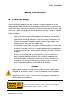
Safety Instructions Safety Instructions Before You Begin Before handling the product, read the instructions and safety guidelines on the following pages to prevent damage to the product and to ensure your own personal safety. Refer to the “Advisories” section in the Preface for advisory conventions used in this user’s guide, including the distinction between Warnings, Cautions, Important Notes, and Notes. Always use caution when handling/operating a computer.
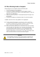
Safety Instructions When Working Inside a Computer Before taking covers off a computer, perform the following steps: 1. Turn off the computer and any peripherals. 2. Disconnect the computer and peripherals from their power sources or subsystems to prevent electric shock or system board damage. This does not apply when hot swapping parts. 3. Follow the guidelines provided in “Preventing Electrostatic Discharge” on the following page. 4.
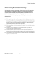
Safety Instructions Preventing Electrostatic Discharge Static electricity can harm system boards. Perform service at an ESD workstation and follow proper ESD procedure to reduce the risk of damage to components. Quanmax strongly encourages you to follow proper ESD procedure, which can include wrist straps and smocks, when servicing equipment.
Safety Instructions Instructions for Lithium Battery WARNING Danger of explosion when battery is replaced with incorrect type. Only replace with the same or equivalent type recommended by the manufacturer. Do not dispose of lithium batteries in domestic waste. Dispose of the battery according to the local regulations dealing with the disposal of these special materials (e.g.
Preface Preface How to Use This Guide This guide is designed to be used as step-by-step instructions for installation, and as a reference for operation, troubleshooting, and upgrades. NOTE Driver downloads and additional information are available under Downloads on our web site: www.quanmax.com. Unpacking When unpacking, follow these steps: 1. After opening the box, save it and the packing material for possible future shipment. 2. Remove all items from the box.
Preface area (domestic environment) is likely to cause harmful interference, in which case the user will be required to correct the interference (take adequate measures) at their own expense. The user is encouraged to try to correct the interference by one or more of the following measures: Reorient or relocate the receiving antenna. Increase the separation between the equipment and receiver. Connect the equipment to an outlet on a circuit different from that to which the receiver is connected.
Preface Return Procedure For any Limited Warranty return, please contact Support at www.quanmax.com and login to obtain a Return Material Authorization (RMA) Number. If you do not have an account, send an email to support@quanmax.com to apply for one. All product(s) returned to Quanmax for service or credit must be accompanied by a Return Material Authorization (RMA) Number.
Preface failure of chips or mechanical failure of devices. If the system has been exposed to abnormally cold temperatures, allow a two-hour warm-up period to bring it up to normal operating temperature before turning it on. Failure to do so may cause damage to internal components, particularly the hard disk drive. Humidity High-humidity can cause moisture to enter and accumulate in the system.
Preface Uninterruptible Power Supply Uninterruptible power supply (UPS) systems offer the most complete protection against variations on power because they use battery power to keep the server running when AC power is lost. The battery is charged by the AC power while it is available, so when AC power is lost, the battery can provide power to the system for a limited amount of time, depending on the UPS system.
Chapter 1 Chapter 1 Introduction Overview The QBOX-2060 is a fanless BOX PC is ideal for space critical applications. This embedded hardware platform is designed with Intel® Atom™ D2550 Processor which provides with excellent performance. The system is supported with Intel® NM10 Express chipset, and DDR3 SO-DIMM up to 4GB. Featured are 1x 2.5” SATA HDD or SSD, 1x mini-PCIe slot, 2x GbE, 4x USB 2.0, 1x DVI-I, 1x HDMI, 4x COMs, 1x mSATA slot, 1x DIO.
Chapter 1 Product Specifications CPU Support ® Intel Atom™ Processor D2550 (1M Cache, 1.86 GHz) Chipset Memory BIOS Graphic External Display LAN Intel NM10 Express chipset 1x Single Channel DDR3 800/1066 MHz SODIMM support (4GB max) AMI Plug & Play SPI BIOS ® Intel Graphics Media Accelerator 3650 1x HDMI 1x DVI-I 2x Gigabit Ethernet (Realtek RTL8111E) PXE/WOL supported Realtek ALC662 HD Codec w/ 2W Audio Amplifier Mic-In, Line-In, Line-Out Supported 1x 2.5” SATA HDD or SSD 1x mSATA 4x USB 2.
Chapter 1 System Tour Refer to the figure below to identify the components of the system. Front Panel Figure 1 Front Panel Power Switch The power button allows powering ON and OFF the system. Power LED (Green) The power LED will light when the PC is power-on. HDD LED (Red) The hard disk LED blinks when data is being written into or read from the HDD. Line Out The stereo headphone jack is used to connect the system’s audio out signal to amplified speakers or headphones.
Chapter 1 Rear Panel Figure 2 Rear Panel DC Jack The supplied power adapter converts AC power to DC for use with this jack. Power supplied through this jack supplies power to the PC. To prevent damage to the PC, always use the supplied power adapter. DVI-I Port The DVI-I (Digital Visual Interface-Integrated) connector allows you to connect an LCD monitor. It provides a high-speed digital interconnection between the computer and its display device.
Chapter 1 Mechanical Dimensions 210 x 35 x135 mm (W x H x D) Figure 3 Mechanical Dimensions QBOX-2060 User’s Manual 19
Chapter 2 Chapter 2 Getting Started Setting up your PC Connect the DVI-I / HDMI cable from your display to the DVI-I / HDMI port. DVI-I HDMI Figure 4 DVI-I / HDMI NOTE When the system reboots without connecting the DVI-I /HDMI, there might be no image on screen when you insert the DVI-I /HDMI cable. Please pressing ++ simultaneously to show the image on screen.
Chapter 2 Connect USB mouse & keyboard Your QBOX-2060 does not come with a keyboard and mouse connector, but you can use any USB keyboard or mouse to connect with your computer. USB Figure 5 Connect USB mouse & keyboard NOTE Using a third-party USB mouse or keyboard may require software drivers. Check the manufacturer’s website for the latest software drivers. Connect LAN port Connect one end of a network cable to the LAN port on the system rear panel and the other end to a hub or switch.
Chapter 2 COM Ports Com ports with the pin definitions.
Chapter 2 Digital Input / Output DIO port with the pin definition.
Chapter 2 Turning on the system 1. Connect the power adapter cable to the DC Jack (DC IN) of the QBOX-2060 2. Connect the power cable to the power adapter 3. Connect the power cable to a power outlet 4.
Chapter 2 Mounting your PC to a monitor Secure the VESA mounting kit to your monitor with four screws. Figure 10 VESA mounting (1) NOTE To fasten the metal shelf, your monitor must comply with VESA75 or VESA100 standard.
Chapter 2 Place the QBOX-2060 onto the monitor and secure it with the hand screw knob properly on VESA mount kit as shown below.
Chapter 3 Chapter 3 AMI BIOS Setup Overview This chapter provides a description of the AMI BIOS. The BIOS setup menus and available selections may vary from those of your product. For specific information on the BIOS for your product, please contact Quanmax. NOTE: The BIOS menus and selections for your product may vary from those in this chapter.
Chapter 3 Main Menu The BIOS Setup is accessed by pressing the DEL key after the Power-On Self-Test (POST) memory test begins and before the operating system boot begins. Once you enter the BIOS Setup Utility, the Main Menu will appear on the screen. The Main Menu provides System Overview information and allows you to set the System Time and Date. Use the “<” and “>” cursor keys to navigate between menu screens.
Chapter 3 Advanced Menu Table 3 Advanced Menu BIOS SETUP UTILITY Main Advanced Boot Security Server Onboard LAN1 Controller [Enabled] Onboard LAN1 Boot Onboard LAN2 Controller Onboard LAN2 Boot Audio Controller [Disabled] [Enabled] [Disabled] [Enabled] Mgmt Save & Select Screen ↑↓ Select Item Enter: Select > CPU Advanced Configuration +- Change Opt.
Chapter 3 Table 4 Advanced Menu – Display Configuration BIOS SETUP UTILITY Main Advanced Boot Security Server Mgmt Save & Display Configuration Fixed Graphics Memory Size IGFX – Boot Type [128 MB] [VBIOS Default] Select Screen ↑↓ Select Item Enter: Select +- Change Opt. F1: General Help F2: Previous Values F3: Optimized Defaults F4 Save & Exit ESC Exit Version 2.14.1219. Copyright (C) 2011, American Megatrends, Inc.
Chapter 3 Table 5 Advanced Menu –Power Management Configuration BIOS SETUP UTILITY Main Advanced Boot Security Server Mgmt Save & Power Management Configuration ACPI Sleep State [S3 (Suspend to RAM)] Restore AC Power Loss Resume from S3 By PS/2 Keyboard Resume from S3 By PS/2 Mouse [Power Off] [Disabled] [Disabled] Resume By PCIE Device [Disabled] Resume By RTC Alarm [Disabled] >Watchdog Timer Configuration Select Screen ↑↓ Select Item Enter: Select +- Change Opt.
Chapter 3 Table 6 Advanced Menu –CPU Advanced Configuration BIOS SETUP UTILITY Main Advanced Boot Security Save & CPU Advanced Configuration Hyper-Treading [Enabled] Execute Disable Bit [Enabled] Limit CPUID Maximum EIST [Disabled] [Enabled] Select Screen ↑↓ Select Item Enter: Select +- Change Opt. F1: General Help F2: Previous Values F3: Optimized Defaults F4 Save & Exit ESC Exit Version 2.14.1219. Copyright (C) 2011, American Megatrends, Inc.
Chapter 3 Table 7 Advanced Menu –SATA Configuration BIOS SETUP UTILITY Main Advanced Boot Security Save & Exit [ AHCI ] Configure SATA as SATA Port 1 SATA Port 2 TOSHIBA MK8046 (80.0G) Not Present Select Screen ↑↓ Select Item Enter: Select +- Change Opt. F1: General Help F2: Previous Values F3: Optimized Defaults F4 Save & Exit ESC Exit Version 2.14.1219. Copyright (C) 2011, American Megatrends, Inc.
Chapter 3 Table 9 Advanced Menu –DIO Configuration BIOS SETUP UTILITY Main Advanced Boot Security Save & DIO Configuration DIO-0 [Output Low] DIO-1 [Output Low] DIO-2 [Output Low] DIO-3 [Output Low] DIO-4 [Output Low] DIO-5 [Output Low] DIO-6 [Output Low] DIO-7 [Output Low] DIO-0 Value 0 DIO-1 Value 0 DIO-2 Value 0 DIO-3 Value 0 DIO-4 Value 0 DIO-5 Value 0 DIO-6 Value 0 DIO-7 Value 0 Select Screen ↑↓ Select Item Enter: Select +- Change Opt.
Chapter 3 Table 10 Advanced Menu – Super IO Configuration BIOS SETUP UTILITY Main Advanced Boot Security Save & Exit Super IO Configuration >Serial Port 1 Configuration >Serial Port 2 Configuration >Serial Port 3 Configuration >Serial Port 4 Configuration Select Screen ↑↓ Select Item Enter: Select +- Change Opt. F1: General Help F2: Previous Values F3: Optimized Defaults F4 Save & Exit ESC Exit Version 2.14.1219. Copyright (C) 2011, American Megatrends, Inc.
Chapter 3 Table 12 Advanced Menu – Super IO Configuration – Serial Port 2 Configuration BIOS SETUP UTILITY Main Advanced Boot Security Save & Serial Port 2 Configuration Serial Port Device Settings Change Settings [Enabled] IO=2F8h; IRQ=3; Select Screen ↑↓ Select Item [Auto] Enter: Select +- Change Opt. F1: General Help F2: Previous Values F3: Optimized Defaults F4 Save & Exit ESC Exit Version 2.14.1219. Copyright (C) 2011, American Megatrends, Inc.
Chapter 3 Table 13 Advanced Menu – Super IO Configuration – Serial Port 3 Configuration BIOS SETUP UTILITY Main Advanced Boot Security Save & Serial Port 3 Configuration Serial Port Device Settings Change Settings [Enabled] IO=3E8h; IRQ=7; Select Screen ↑↓ Select Item [Auto] Enter: Select +- Change Opt. F1: General Help F2: Previous Values F3: Optimized Defaults F4 Save & Exit ESC Exit Version 2.14.1219. Copyright (C) 2011, American Megatrends, Inc.
Chapter 3 Table 14 Advanced Menu – Super IO Configuration – Serial Port 4 Configuration BIOS SETUP UTILITY Main Advanced Boot Security Save & Serial Port 4 Configuration Serial Port Device Settings Change Settings [Enabled] IO=2E8h; IRQ=7; Select Screen ↑↓ Select Item [Auto] Enter: Select +- Change Opt. F1: General Help F2: Previous Values F3: Optimized Defaults F4 Save & Exit ESC Exit Version 2.14.1219. Copyright (C) 2011, American Megatrends, Inc.
Chapter 3 Table 15 Advanced Menu –H/W Monitor BIOS SETUP UTILITY Main Advanced Boot Security Save & PC Health Status CPU Warning Temperature [Enabled] CPU Temperature : +50 C : +42 C SYS Temperature +VCORE +VGFX +3.3V +5V +VIN +1.05V +1.5V +VSBVCC Select Screen ↑↓ Select Item Enter: Select +- Change Opt. F1: General Help F2: Previous Values F3: Optimized Defaults F4 Save & Exit ESC Exit Version 2.14.1219. Copyright (C) 2011, American Megatrends, Inc. : +0.832 V : +1.024 V : +3.392 V : +4.
Chapter 3 Boot Menu Table 16 Boot Menu BIOS SETUP UTILITY Main Advanced Boot Boot Configuration Full Screen LOGO Display [Disabled] Setup Prompt Timeout Bootup NumLock State 1 [On] Security Save & Select Screen ↑↓ Select Item Enter: Select Boot Option #1 [UEFI: SanDisk] +- Change Opt. Boot Option#2 [SATA PM: TOSHIBA…] F1: General Help Hard Drive BBS Priorities F2: Previous Values F3: Optimized Defaults F4 Save & Exit ESC Exit Version 2.14.1219. Copyright (C) 2011, American Megatrends, Inc.
Chapter 3 Security Menu Table 17 Security Menu BIOS SETUP UTILITY Main Advanced Boot Security Save & Exit Password Description If ONLY the Administrator’s password is set, then this only limits access to Setup and is only asked for when entering Setup If ONLY the User’s password is set, then this is a power on password and must be entered to boot or enter Setup.
Chapter 3 Save Changes and Exit Exit system setup after saving the changes. Once you are finished making your selections, choose this option from the Exit menu to ensure the values you selected are saved to the CMOS RAM. The CMOS RAM is sustained by an onboard backup battery and stays on even when the PC is turned off. When you select this option, a confirmation window appears. Select [Yes] to save changes and exit. Discard Changes and Exit Exit system setup without saving any changes.
Chapter 4 Chapter 4 Driver Installation If your QBOX-2060 does not come with an operating system pre-installed, you will need to install an operating system and the necessary drivers to operate it. After you have finished assembling your system and connected the appropriate power source, power it up using the power supply and install the desired operating system. You can download the drivers for the QBOX-2060 from the Quanmax website at www.quanmax.com and install as instructed there.