QutePC-4100 Series 0.
Contact Info: Quanmax Inc. 5F, No. 415, Ti-Ding Blvd. Sec. 2, NeiHu District, Taipei, Taiwan 114 Tel: +886-2-2799-2789 Fax: +886-2-2799-7399 Visit our site at: www.quanmax.com © 2013 Quanmax Inc. All rights reserved. The information in this user’s guide is provided for reference only. Quanmax does not assume any liability arising out of the application or use of the information or products described herein.
Content Content Content....................................................................................................................... 3 Figures & Tables......................................................................................................... 4 Safety Instructions ...................................................................................................... 5 Before You Begin ..................................................................................
Figures & Tables Figures & Tables Figure 1 Front Panel .................................................................................. 15 Figure 2 Rear Panel ................................................................................... 16 Figure 3 Mechanical Dimensions ............................................................... 18 Figure 4 DP/ HDMI ..................................................................................... 19 Figure 5 Connecting USB mouse & keyboard..................
Safety Instructions Safety Instructions Before You Begin Before handling the product, read the instructions and safety guidelines on the following pages to prevent damage to the product and to ensure your own personal safety. Refer to the “Advisories” section in the Preface for advisory conventions used in this user’s guide, including the distinction between Warnings, Cautions, Important Notes, and Notes. Always use caution when handling/operating a computer.
Safety Instructions When Working Inside a Computer Before taking covers off a computer, perform the following steps: 1. Turn off the computer and any peripherals. 2. Disconnect the computer and peripherals from their power sources or subsystems to prevent electric shock or system board damage. This does not apply when hot swapping parts. 3. Follow the guidelines provided in “Preventing Electrostatic Discharge” on the following page. 4.
Safety Instructions remove the component’s antistatic packing material until you are ready to install the component in a computer. Just before unwrapping the antistatic packaging, be sure you are at an ESD workstation or grounded. This will discharge any static electricity that may have built up in your body. When transporting a sensitive component, first place it in an antistatic container or packaging. Handle all sensitive components at an ESD workstation.
Preface Preface How to Use This Guide This guide is designed to be used as step-by-step instructions for installation, and as a reference for operation, troubleshooting, and upgrades. NOTE Driver downloads and additional information are available under Downloads on our web site: www.quanmax.com. Unpacking When unpacking, follow these steps: 1. After opening the box, save it and the packing material for possible future shipment. 2. Remove all items from the box.
Preface interference to radio or television equipment reception, which can be determined by turning the equipment off and on, the user is encouraged to try to correct the interference by one or more of the following measures: Reorient or relocate the receiving antenna. Increase the separation between the equipment and receiver. Connect the equipment to an outlet on a circuit different from that to which the receiver is connected. Consult the dealer or an experienced radio/TV technician for help.
Preface account, send an email to support@quanmax.com to apply for one. All product(s) returned to Quanmax for service or credit must be accompanied by a Return Material Authorization (RMA) Number. Freight on all returned items must be prepaid by the customer who is responsible for any loss or damage caused by common carrier in transit. Returns for Warranty must include a Failure Report for each unit, by serial number(s), as well as a copy of the original invoice showing the date of purchase.
Preface turning it on. Failure to do so may cause damage to internal components, particularly the hard disk drive. Humidity High-humidity can cause moisture to enter and accumulate in the system. This moisture can cause corrosion of internal components and degrade such properties as electrical resistance and thermal conductivity. Extreme moisture buildup inside the system can result in electrical shorts, which can cause serious damage to the system.
Preface Line conditioners keep a system’s AC power source voltage at a fairly constant level and, therefore, can handle brownouts. Because of this added protection, line conditioners cost more than surge protectors. However, line conditioners cannot protect against a complete loss of power. Uninterruptible Power Supply Uninterruptible power supply (UPS) systems offer the most complete protection against variations on power because they use battery power to keep the server running when AC power is lost.
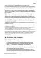
Chapter 1 Chapter 1 Introduction Overview The QutePC-4100 Series is a Box PC with a volume of just 0.6-liter that is ideal for space critical applications. This embedded hardware platform is designed with Intel® 3rd generation Core i3-3227U Processor which provides the excellent performance. System is supported with Intel® HM76 Express chipset, and DDR3 SO-DIMM up to 8GB. Featured are 1x 2.5” SATA HDD, 2x GbE, 4x USB3.0, 2x USB2.0, HDMI, 2xDP.
Chapter 1 Product Specifications Construction Plastic Casing Intel® 3rd generation Core i3-3227U Processor Intel® HM76 Express Chipset QutePC-4100 : 1x DDR3 SO-DIMM up to 4GB QutePC-4101 : 1x DDR3 SO-DIMM up to 2GB QutePC-4102 : 1x DDR3 SO-DIMM up to 2GB ■ Front I/O panel 1x Push button (w/LED) for power on/off 1x WiFi LED 1x HDD LED 2x USB2.0 4x USB3.0 1x S/PDIF ■ Rear I/O panel 1x DC JACK 2x RJ-45, GbE ports 2x DP 1x HDMI 1x 3G Antenna ( Optional ) 1x Clear CMOS QutePC-4100 : 1x 500GB 2.
Chapter 1 System tour Refer to the diagrams below to identify the components of the system. Front Panel Figure 1 Front Panel USB The USB (Universal Serial Bus) port is compatible with USB devices such as keyboards, mouse devices, cameras, and hard disk drives. USB allows many devices to run simultaneously on a single computer, with some peripheral acting as additional plug-in sites or hubs. WiFi LED The WiFi LED will light when the WiFi is on.
Chapter 1 Rear Panel Figure 2 Rear Panel Ethernet The eight-pin RJ-45 LAN port supports a standard Ethernet cable for connection to a local network. DC Jack The supplied power adapter converts AC power to DC for use with this jack. Power supplied through this jack supplies power to the PC. To prevent damage to the PC, always use the supplied power adapter. Kensington Lock Slot The slot is used for attaching a lock-and-cable apparatus.
Chapter 1 Wireless 1x reserved holes for wireless antenna connections. Clear CMOS 1x reset button for clear CMOS.
Chapter 1 Mechanical Dimensions 130 x 38.5 x 115.
Chapter 2 Chapter 2 Getting Started Setting up your PC Connecting the monitor Connect the DP/ HDMI cable from your display to the DP/ HDMI port.
Chapter 2 Connecting USB mouse & keyboard Your QutePC-4100 series does not come with a keyboard and mouse, but you can use any USB keyboard or mouse with your computer. USB 3.0 USB 2.0 Figure 5 Connecting USB mouse & keyboard NOTE Using a third-party USB mouse or keyboard may require software drivers. Check the manufacturer’s website for the latest software drivers.
Chapter 2 Connecting to a network device Connect one end of a network cable to the LAN port on the system rear panel and the other end to a hub or switch. RJ45 Figure 6 RJ45 connector Turning on the system 1. 2. 3. 4.
Chapter 2 Mounting your PC to a monitor 1. Secure the VESA mounting kit to your monitor with four screws. NOTE To fasten the metal shelf, your monitor must comply with VESA75 or VESA100 standard. The VESA mounting kit is optional. 2. 3. Place the QutePC-4100 series on the VESA mounting bracket and make sure the bracket is hooked with the fins of the system housing. Secure the screw with the VESA mounting bracket and make sure the QutePC-4100 series is solidly secured to the display.
Chapter 2 Anti-theft protection with a Kensington Lock The QutePC-4100 series has a Kensington lock slot for the Kensington MicroSaver. With the Kensington MicroSaver, a sturdy steel cable, you can attach your QutePC-4100 series to a stationary object and protect your PC from theft.
Chapter 3 Chapter 3 AMI BIOS Setup Overview This chapter provides a description of the AMI BIOS. The BIOS setup menus and available selections may vary from those of your product. For specific information on the BIOS for your product, please contact Quanmax. NOTE: The BIOS menus and selections for your product may vary from those in this chapter.
Chapter 3 Main Menu The BIOS Setup is accessed by pressing the DEL key after the Power-On Self-Test (POST) memory test begins and before the operating system boot begins. Once you enter the BIOS Setup Utility, the Main Menu will appear on the screen. The Main Menu provides System Overview information and allows you to set the System Time and Date. Use the “<” and “>” cursor keys to navigate between menu screens.
Chapter 3 Advanced Menu Table 3 Advanced Menu BIOS SETUP UTILITY Main Advanced Boot Security Server Mgmt Save & Exit Onboard LAN 1 Controller [Enabled] Select Screen Onboard LAN 1 Boot [Disabled] ↑↓ Select Item Onboard LAN 2 Controller [Enabled] Enter: Select Onboard LAN 2 Boot [Disabled] +- Change Opt.
Chapter 3 Table 4 Advanced Menu – Display Configuration BIOS SETUP UTILITY Main Advanced Boot Security Server Mgmt Save & Exit Select Screen Display Configuration Aperture Size [256 MB] ↑↓ Select Item DVMT Pre-Allocated [64 MB] Enter: Select DVMT Total Gfx Mem [256 MB] +- Change Opt. IGFX – Boot Type [ VBIOS Default] F1: General Help F2: Previous Values F3: Optimized Defaults F4 Save & Exit ESC Exit Version 2.15.1236. Copyright (C) 2012, American Megatrends, Inc.
Chapter 3 Table 5 Advanced Menu –Power Management Configuration BIOS SETUP UTILITY Main Advanced Boot Security Server Save & Exit Select Screen Power Management Configuration ACPI Sleep State Mgmt [S3 (Suspend to RAM)] Restore AC Power Loss Resume By PCIE Device Resume By RTC Alarm [Power Off] [Disabled] [Disabled] EUP Power Saving Mode [Disabled] >Watchdog Timer Configuration ↑↓ Select Item Enter: Select +- Change Opt.
Chapter 3 Table 6 Advanced Menu –CPU Advanced Configuration BIOS SETUP UTILITY Main Advanced Boot Security [Enabled] Active Processor Cores Limit CPUID Maximum Execute Disable Bit Intel Virtualization Technology & Select Screen CPU Advanced Configuration EIST Save ↑↓ Select Item Enter: Select [ALL] [Disabled] [Enabled] [Disabled] +- Change Opt. F1: General Help F2: Previous Values F3: Optimized Defaults F4 Save & Exit ESC Exit Version 2.15.1236. Copyright (C) 2012 American Megatrends, Inc.
Chapter 3 Table 7 Advanced Menu –SATA Configuration BIOS SETUP UTILITY Main Advanced SATA Controller(s) Boot Security [ AHCI] [ Default] Serial ATA Port 0 Software Preserve Port 0 SATA Device Type Empty Unknown [ Enabled ] [ Hard Disk Driver] & Exit Select Screen [Enabled] SATA Mode Selection SATA Controller Speed Save ↑↓ Select Item Enter: Select +- Change Opt. F1: General Help F2: Previous Values F3: Optimized Defaults F4 Save & Exit ESC Exit Version 2.15.1236.
Chapter 3 Table 9 Advanced Menu –USB Configuration BIOS SETUP UTILITY Main Advanced Boot Security Save & Select Screen USB Configuration ↑↓ Select Item USB Devices: Enter: Select +- Change Opt. 1 Keyboard, 1 Mouse, 2 Hubs Legacy USB Support [Enabled] F1: General Help USB3.
Chapter 3 Table 10 Advanced Menu –H/W Monitor BIOS SETUP UTILITY Main Advanced Boot Security Save & PC Health Status CPU Warning Temperature CPU FAN Configuration CPU Temperature Memory Temperature System Temperature [Disabled] : +55 C : +36 C : +42 C CPU FAN Speed N/A +VCORE +VIN 5V +1.05V +3.3VSB +3.3V VBAT : +0.736V : +19.447V : +5.044V : +1.056V : +3.376V : +3.312V : +3.344V Select Screen ↑↓ Select Item Enter: Select +- Change Opt.
Chapter 3 Boot Menu Table 11 Boot Menu BIOS SETUP UTILITY Main Advanced Boot Security Save & Select Screen Boot Configuration Full Screen LOGO Display [Disabled] ↑↓ Select Item Setup Prompt Timeout Bootup NumLock State 1 [On] Enter: Select UEFI Boot [Disabled] +- Change Opt. F1: General Help F2: Previous Values Boot Option Priorities F3: Optimized Defaults F4 Save & Exit ESC Exit Version 2.15.1236. Copyright (C) 2012 American Megatrends, Inc.
Chapter 3 Security Menu Table 12 Security Menu BIOS SETUP UTILITY Main Advanced Boot Security Save & Exit Password Description If ONLY the Administrator’s password is set, then this only limits access to Setup and is only asked for when entering Setup Select Screen If ONLY the User’s password is set, then this is a power on password and must be entered to boot or enter Setup.
Chapter 3 Save Changes and Exit Exit system setup after saving the changes. Once you are finished making your selections, choose this option from the Exit menu to ensure the values you selected are saved to the CMOS RAM. The CMOS RAM is sustained by an onboard backup battery and stays on even when the PC is turned off. When you select this option, a confirmation window appears. Select [Yes] to save changes and exit. Discard Changes and Exit Exit system setup without saving any changes.
Chapter 4 Chapter 4 Driver Installation If your QutePC-4100 series does not come with an operating system pre-installed, you will need to install an operating system and the necessary drivers to operate it. After you have finished assembling your system and connected the appropriate power source, power it up using the power supply and install the desired operating system. You can download the drivers for the QutePC-4100 from the Quanmax website at www.quanmax.com and install as instructed there.