
User manual


6 TESTING AND TROUBLESHOOT-
ING
This section describes some functional tests to determine if the Ball and Beam system is operating properly. It is
assumed that the system is connected as described in the Section 5, above. To carry out these tests, it is preferable
if the user uses a software such as QUARC
r
or LabVIEW
TM
to read sensor measurements and ouput voltages to
the motor. See Reference [1] to learn how to interface the SRV02 with QUARC. Alternatively, these tests can be
performed with a signal generator and an oscilloscope.
6.1 SRV02 Motor and Encoder
See [2] for information on testing and troubleshooting the SRV02 separately.
6.2 Ball Position Sensor
6.2.1 Testing
Test the ball position sensor from the BB01 or SS01 with the following procedure:
1. Measure analog input channel #2 to test the BB01 sensor or analog input channel #3 to test the SS01 sensor
(unless the sensors are connected on a different channels).
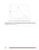
2. A typical signal response of the ball position sensor is illustrated in Figure 6.1. For the BB01, the ball position
sensor should output a voltage of about 4.5 V when it is closest to the SRV02. As the ball is rolled away from
the SRV02 the measured voltage signal should be decreasing down to approximately -4.5 V when the ball
reaches the other end of the beam.
Caution: Sometimes when the ball is sitting at the very end of the beam it may not be in contact with the
sensor. In this case the reading will initially be 0 V but when the ball begins moving the sensor signal will jump
up to about 4.5 V and then begin decreasing.
3. Beside the ends of the beam, the signal should have no discontinuities and little noise. Similarly for the SS01
sensor, the voltage signal should decreasing from approximately 4.5 V to -4.5 V as the ball travels towards the
end of the beam with the analog connector.
6.2.2 Troubleshooting
Follow the steps below if the potentiometer is not measuring correctly:
• Verify that the power amplifier is functional. For example when using the Quanser VoltPAQ device, is the
green LED lit? Recall the analog sensor signal go through the amplifier before going to the data-acquisition
device (except when using the Q3 ControlPAQ). Therefore the amplifier needs to be turned on to read the
potentiometer.
• Check that the data-acquisition board is functional, e.g. ensure it is properly connected, that the fuse is not
burnt.
• Measure the voltage across the potentiometer. Ensure the potentiometer is powered with a ±12 V at the 6-
pin-mini DIN connector on the BB01, component #10 in Figure 2.1, or on the SS01, component #14 in Figure
2.2. The two bottom pins of the DIN connector are GND pins and the leftmost pin, i.e. where the green cable
is connected to, outputs the voltage of the ball.
BB01 User Manual 14