Ten modules to teach controls from the basic to advanced level SRV02 Base Unit Flexible Link Inverted Pendulum Ball and Beam USER MANUAL SRV02 Rotary Servo Base Unit Set Up and Configuration 2 DOF Robot Flexible Joint 2 DOF Inverted Pendulum Gyro/Stable Platform Multi-DOF Torsion Double Inverted Pendulum Developed by: Jacob Apkarian, Ph.D., Quanser Michel Lévis, M.A.Sc., Quanser Hakan Gurocak, Ph.D.
c 2011 Quanser Inc., All rights reserved. ⃝ Quanser Inc. 119 Spy Court Markham, Ontario L3R 5H6 Canada info@quanser.com Phone: 1-905-940-3575 Fax: 1-905-940-3576 Printed in Markham, Ontario. For more information on the solutions Quanser Inc. offers, please visit the web site at: http://www.quanser.com This document and the software described in it are provided subject to a license agreement.
CONTENTS 1 Presentation 1.1 Description 1.2 Rotary Modules and Experiment Overview 4 4 4 2 SRV02 Components 2.1 SRV02 Component Nomenclature 2.2 Component Description 2.3 SRV02-ETS Components 6 6 6 8 3 SRV02 Specifications 11 4 SRV02 Setup and Configuration 4.1 Gear Configuration 4.2 Load Configurations 13 13 14 5 Wiring Procedure 5.1 Cable Nomenclature 5.2 Typical Connections 5.3 Connections for VoltPAQ-X2 15 15 16 18 6 Testing and Troubleshooting 6.1 Motor 6.2 Potentiometer 6.
1 PRESENTATION 1.1 Description The Quanser SRV02 rotary servo plant, pictured in Figure 1.1, consists of a DC motor that is encased in a solid aluminum frame and equipped with a planetary gearbox. The motor has its own internal gearbox that drives external gears. The SRV02 is equipped with three sensors: potentiometer, encoder, and tachometer. The potentiometer and encoder sensors measure the angular position of the load gear and the tachometer can be used to measured its velocity. Figure 1.
System SRV02 SRV02 Experiment SRV02 QUARC Integration Modeling SRV02 Position Control SRV02 Speed Control Ball and beam Balance Control Flexible Joint Vibration Control Flexible Link Vibration Control Single Pendulum Self-Erecting Single Inverted Pendulum Control Double Pendulum Double-Inverted Pendulum Balance Control Gyroscope Heading Control 1-DOF Torsion Vibration Control 2 DOF Torsion Vibration Control 2 DOF Robot 2D Task-Based Position Control 2 DOF Pendulum 2 DOF Gantry Contr
2 SRV02 COMPONENTS The SRV02 components are identified in Section 2.1. Some of the those components are then described in Section 2.2. 2.1 SRV02 Component Nomenclature The SRV02 components listed in Table 2.1 below are labeled in figures 2.1a, 2.1b, 2.1c, 2.1d, and 2.1e. Note that Figure 2.1a shows the SRV02 in the low-gear configuration and Figure 2.1b is the SRV02 in the high-gear configuration. These different gear setups will be explained later in Section 4.1.
Figure 2.2: SRV02 potentiometer wiring As illustrated in Figure 2.2, the potentiometer is connected to a ±12 V DC power supply through two 7.15 kΩ bias resistors. Under normal operations, terminal 1 should measure -5 V while terminal 3 should measure 5 V. The actual position signal is available at terminal 2. 2.2.3 Tachometer The SRV02-T and SRV02-ET models come equipped with a tachometer that is directly attached to the DC motor and is depicted with ID #13 in Figure 2.1c.
potentiometer which measures the absolute angle). Figure 2.4: SRV02 encoder wiring The position signal generated by the encoder can be directly connected to the data-acquisition device using a standard 5-pin DIN cable. The internal wiring of the encoder and the 5-pin DIN connector on the SRV02, component #17, is illustrated in Figure 2.4. Caution: amplifier. Make sure you connect the encoder directly to your data-acquistion device and not to the power 2.
(a) Low-gear (b) High-gear (c) Front view (d) Connectors (e) Inertial Loads Figure 2.1: SRV02 components SRV02 User Manual v 1.
Figure 2.5: SRV02-ETS Figure 2.
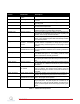
3 SRV02 SPECIFICATIONS Table 3.1 lists and characterizes the main parameters associated with the SRV02. Some of these are used in the mathematical model. More detailed information about the gears is given in Table 3.2 and the calibration gains for the various sensors on the SRV02 are summarized in Table 3.3.
Symbol Kgi Kge,low Kge,high m24 m72 m120 r24 r72 r120 Description Internal gearbox ratio Internal gearbox ratio (low-gear) Internal gearbox ratio (high-gear) Mass of 24-tooth gear Mass of 72-tooth gear Mass of 120-tooth gear Radius of 24-tooth gear Radius of 72-tooth gear Radius of 120-tooth gear Matlab Variable Kgi Kge Kge m24 m72 m120 r24 r72 r120 Value 14 1 5 0.005 kg 0.030 kg 0.083 kg 6.35 × 10⁻³ m 0.019 m 0.032 m Table 3.
4 SRV02 SETUP AND CONFIGURATION As discussed in Section 4.1, the SRV02 can be setup with two different gear configurations depending on the experiment being performed. Also, Section 4.2 shows how the SRV02 can be fitted with different loads. 4.1 Gear Configuration 4.1.1 Description The SRV02 can be setup in the low-gear configuration or the high-gear configuration, as pictured in Figure 4.1a and Figure 4.1b, respectively.
Note: The potentiometer gear, component #6 in Figure 2.1b, is an anti-backlash gear and special precaution need to be taken when installing it. In order to insert it properly, rotate its two faces against each other such that the springs are partially pre-loaded. Do not fully extend the springs when you pre-load the gears. 4. Ensure the teeth of all the three gears are meshed together. Remark that in the high-gear setup, the top 72-tooth load gear is meshed with the potentiometer gear, ID #6 in Figure 2.1b.
5 WIRING PROCEDURE The following is a listing of the hardware components used in this experiment: 1. Power Amplifier: Quanser VoltPAQ-X1, or equivalent. 2. Data Acquisition Board: Quanser QPID, QPIDe, Q8-USB, Q2-USB, or equivalent. 3. Rotary Servo Plant: Quanser SRV02-ET, SRV02-ETS, or equivalent. See the corresponding documentation for more information on these components. The cables supplied with the SRV02 are described in Section Section 5.
Cable Type 2xRCA to 2xRCA Description This cable connects an analog output of the data acquisition terminal board to the power module for proper power amplification. 4-pin-DIN to 6-pinDIN This cable connects the output of the power module, after amplification, to the desired DC motor on the servo. 5-pin-stereo-DIN to 5-pin-stereo-DIN This cable carries the encoder signals between an encoder connector and the data acquisition board (to the encoder counter).
1. Make sure that your data-acquisition device is installed and is operational. For example, if using the Quanser Q2-USB see Reference [5]. 2. Make sure everything is powered off before making any of these connections. This includes turning off your PC and the amplifier. 3. Connect one end of the 2xRCA to 2xRCA cable from the Analog Output Channel #0 on the terminal board to the Amplifier Command connector on the amplifier, i.e. use both white or both red RCA connectors. See cable #1 shown in Figure 5.1.
Figure 5.1: Connecting the SRV02 to a Single-Channel Amplifier and Two-Channel DAQ 5.3 Connections for VoltPAQ-X2 Some amplifiers, such as the Quanser VoltPAQ-X2, need to be enabled and have an emergency switch connected. The amplifier may not have an analog sensor interface built-in either - requiring an external device. This section describes the wiring required for that configuration. The connections are summarized in Table 5.3 and depicted in Figure 5.2. Note: The wiring diagram shown in Figure 5.
Cable # 1 2 3 4 5 6 7 8 9 From To Signal Terminal Board: Analog Output #0 Amplifier: To Load connector Terminal Board: Encoder Input #0 Analog Signal Conditioner S1 Output Analog Signal Conditioner S2 Output SRV02 S1 & S2 connector Analog Signal Conditioner Input 1 connector Amplifier Amplifier Command connector SRV02 Motor connector Control signal to the amplifier.
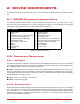
6 TESTING AND TROUBLESHOOTING This section describes some functional tests to determine if your SRV02 is operating normally. It is assumed that the SRV02 is connected as described in the Section 5, above. To carry out these tests, it is preferable if the user can use a software such as QUARCr or LabVIEWr to read sensor measurements and feed voltages to the motor. See Reference [4] to learn how to interface the SRV02 with QUARC.
6.2.2 Troubleshooting Follow the steps below if the potentiometer is not measuring correctly:: • Verify that the power amplifier is functional. For example when using the Quanser VoltPAQ device, is the green LED lit? Recall the analog sensor signal go through the amplifier before going to the data-acquisition device (except when using the Q3 ControlPAQ). Therefore the amplifier needs to be turned on to read the potentiometer. • Check that the data-acquisition board is functional, e.g.
2. Rotate the SRV02 load gear, component #5 in Figure 2.1b, one rotation and the encoder should measure 4096 counts (or 8192 when using the SRV02-EHR option) in quadrature mode. Note: Some data acquisition systems do not measure in quadrature and, in this case, one-quarter of the expected counts are received, i.e. 1024 counts in the SRV02-E or 2048 in the SRV02-EHR. In addition, some data acquisition systems measure in quadrature but increment the count by 0.
7 TECHNICAL SUPPORT To obtain support from Quanser, go to http://www.quanser.com/ and click on the Tech Support link. Fill in the form with all the requested software and hardware information as well as a description of the problem encountered. Also, make sure your e-mail address and telephone number are included. Submit the form and a technical support person will contact you. SRV02 User Manual v 1.
REFERENCES [1] US Digital. E2 optical kit encoder. 2007. [2] Faulhaber. Dc-micromotors series 2338. 2002. [3] Faulhaber. Dc-motor-tacho combinations. 2002. [4] Quanser Inc. Srv02 quarc integration. 2008. [5] Quanser Inc. Q2-usb data-acquisition system user's guide. 2010. [6] Vishay Spectrol. Model 132, 138, 139. 2001.
Ten modules to teach controls from the basic to advanced level SRV02 Base Unit Flexible Link Inverted Pendulum Ball and Beam USER MANUAL SRV02 Rotary Servo Base Unit Set Up and Configuration 2 DOF Robot Flexible Joint 2 DOF Inverted Pendulum Gyro/Stable Platform Multi-DOF Torsion Double Inverted Pendulum Developed by: Jacob Apkarian, Ph.D., Quanser Michel Lévis, M.A.Sc., Quanser Hakan Gurocak, Ph.D.