
User manual
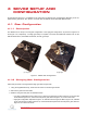
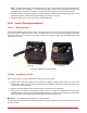


Table Of Contents

4 SRV02 SETUP AND
CONFIGURATION
As discussed in Section 4.1, the SRV02 can be setup with two different gear configurations depending on the ex-
periment being performed. Also, Section 4.2 shows how the SRV02 can be fitted with different loads.
4.1 Gear Configuration
4.1.1 Description
The SRV02 can be setup in the low-gear configuration or the high-gear configuration, as pictured in Figure 4.1a
and Figure 4.1b, respectively. The high-gear setup is required to be used with additional modules such as the
ball-and-beam device, the flexible link module, and the gyroscope.
(a) Low-gear (b) High-gear
Figure 4.1: SRV02 Gear Configurations
4.1.2 Changing Gear Configuration
Follow this procedure to change between high-gear and low-gear ratio:
1. Using the supplied Allen keys, loosen the set screws on the three gear shafts.
2. Remove the gears from the shafts.
3. Slide the new gears into place as described below:
• Low-gear configuration shown in Figure 4.1a: place the 72-tooth gear, ID #5 in Figure 2.1a, onto the load
shaft, ID #8 in Figure 2.1a, and the 72-tooth pinion gear, ID #4 in Figure 2.1a, on the motor shaft.
• High-gear configuration depicted in Figure 4.1b: slide the 120-tooth gear, ID #20 in Figure 2.1b, followed
by the 72-tooth gear, ID #8 in Figure 2.1b, on the load shaft and place the 20-tooth pinion gear, ID #19 in
Figure 2.1b, on the motor shaft.
SRV02 User Manual
v 1.0