
User manual
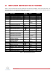
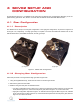
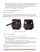
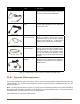


Table Of Contents

Note: The potentiometer gear, component #6 in Figure 2.1b, is an anti-backlash gear and special precaution
need to be taken when installing it. In order to insert it properly, rotate its two faces against each other such
that the springs are partially pre-loaded. Do not fully extend the springs when you pre-load the gears.
4. Ensure the teeth of all the three gears are meshed together. Remark that in the high-gear setup, the top
72-tooth load gear is meshed with the potentiometer gear, ID #6 in Figure 2.1b.
5. Tighten the set-screws on each shaft with the supplied Allen keys.
4.2 Load Configurations
4.2.1 Description
The SRV02 is supplied with two external loads: a bar and a disk. These can be attached to the SRV02 load gear
to vary the moment of inertia seen at the output. The SRV02 with the end of the bar load connected is pictured in
Figure 4.2a. Either the end of the bar or the center of the bar can be used. In Figure 4.2b the SRV02 with the disk
load attached is shown.
(a) Bar load (b) Disc load
Figure 4.2: SRV02 Load Configurations
4.2.2 Installing Load
Follow this procedure to connect either the bar or disc load to the load gear:
1. Slide the center hole of the load on the output shaft of the SRV02, component #8 in Figure 2.1b. For the bar
load (ID #21 in Figure 2.1e), use either the center hole in the middle of the bar or the center hole at the an end
of the bar onto the output shaft.
2. Align the two holes adjacent to the center hole with the screw holes of the load gear.
3. Using the two 8-32 thumb screws provided, ID #23 in Figure 2.1e, fasten the inertial load to the output gear.
The SRV02 with the bar load and the disk load attached is shown in Figure 4.2a and Figure 4.2b, respectively.
Make sure all the screws are properly tightened before operating the servo unit.
Caution: Do not apply a load that weighs over 5 kg at any time.
For instructions on how to install one the SRV02 modules (e.g. rotary flexible joint) see the user manual correspond-
ing to that module.
SRV02 User Manual 14