
User manual
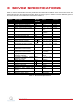
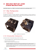
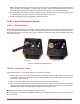
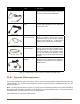


Table Of Contents

Cable Type Description
(a) RCA Cable
2xRCA to 2xRCA This cable connects an analog output of the
data acquisition terminal board to the power
module for proper power amplification.
(b) Motor Cable
4-pin-DIN to 6-pin-
DIN
This cable connects the output of the power
module, after amplification, to the desired DC
motor on the servo.
(c) Encoder Cable
5-pin-stereo-DIN to
5-pin-stereo-DIN
This cable carries the encoder signals be-
tween an encoder connector and the data
acquisition board (to the encoder counter).
Namely, these signals are: +5 VDC power
supply, ground, channel A, and channel B
(d) Analog Cable
6-pin-mini-DIN to
6-pin-mini-DIN
This cable carries analog signals (e.g., from
joystick, plant sensor) to the amplifier, where
the signals can be either monitored and/or
used by a controller. The cable also carries
a ± 12 VDC line from the amplifier in order
to power a sensor and/or signal conditioning
circuitry.
(e) 5-pin-DIN to 4xRCA
5-pin-DIN to
4xRCA
This cable carries the analog signals, un-
changed, from the amplifier to the Digital-To-
Analog input channels on the data acquisition
terminal board.
Table 5.1: Cables used to connect SRV02 to amplifier and DAQ device
5.2 Typical Connections
This section describes the typical connections used to connect the SRV02 plant to a data-acquisition board and
a power amplifier. The connections are described in detail in the procedure below, summarized in Table 5.2, and
pictured in Figure 5.1.
Note: The wiring diagram shown in Figure 5.1 is using a two-channel data-acquisition board, which resembles a
Quanser Q2-USB. The same connections can be applied for any data-acquisition system - as long as it has least
two analog input, two analog output, and two encoder channels.
Follow these steps to connect the SRV02 system:
SRV02 User Manual 16