
User manual
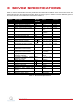
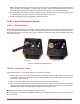
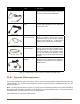


Table Of Contents

1. Make sure that your data-acquisition device is installed and is operational. For example, if using the Quanser
Q2-USB see Reference [5].
2. Make sure everything is powered off before making any of these connections. This includes turning off your
PC and the amplifier.
3. Connect one end of the 2xRCA to 2xRCA cable from the Analog Output Channel #0 on the terminal board
to the Amplifier Command connector on the amplifier, i.e. use both white or both red RCA connectors. See
cable #1 shown in Figure 5.1. This carries the attenuated motor voltage control signal, V
m
/K
a
, where K
a
is
the amplifier gain.
4. Connect the 4-pin-stereo-DIN to 6-pin-stereo-DIN that is labeled from To Load on the amplifier to the Motor
connector on the SRV02. See connection #2 shown in Figure 5.1. The cable transmits the amplified voltage
that is applied to the SRV02 motor and is denoted V
m
.
5. Connect the 5-pin-stereo-DIN to 5-pin-stereo-DIN cable from the Encoder connector on the SRV02 panel to
Encoder Input # 0 on the terminal board, as depicted by connection #3 in Figure 5.1. This carries the load
shaft angle measurement and is denoted by the variable θ
l
.
Caution: Any encoder should be directly connected to the data-acquisition terminal board (or equivalent)
using a standard 5-pin DIN cable. DO NOT connect the encoder cable to the amplifier!
6. Connect the To ADC socket on the amplifier to Analog Inputs #0-1 on the terminal board using the 5-pin-DIN
to 4xRCA cable, as illustrated in Figure 5.1. The RCA side of the cable is labeled with the channels: yellow is
S1, white is S2, red is S3, and black is S4. The yellow S1 connector goes to Analog Input Channel #0 and the
white S2 connector goes to Analog Input Channel #1.
7. Connect the TACH connector on the SRV02 to the S1 & S2 socket on the SRV02 using the 6-pin-mini-DIN
to 6-pin-mini-DIN cable. This connection is labeled #5 in Figure 5.1. It combines the potentiometer (S1)
measurement with the tachometer (S2) measurement.
8. Connect the S1 & S2 connector on the SRV02 to the S1 & S2 socket on the amplifier using the 6-pin-mini-DIN
to 6-pin-mini-DIN cable. See connection #6 in Figure 5.1. This carries the potentiometer (S1) and tachometer
(S2) signals. The measured load shaft rate from the tachometer is denoted by the variable ω
l
and the load
shaft angle is represented by variable θ
l
.
Cable
#
From To Signal
1 Terminal Board: Analog
Output #0
Amplifier Amplifier Command
connector
Control signal to the amplifier.
2 Amplifier: To Load con-
nector
SRV02 Motor connector Power leads to the SRV02 dc motor.
3 Terminal Board: Encoder
Input #0
SRV02 Encoder connector Encoder load shaft angle measure-
ment.
4 Amplifier: To ADC con-
nector
Terminal Board:
• S1 to Analog Input #0
• S2 to Analog Input #1
Connects analog sensor signals S1
and S2 to Analog Input Channels #0
and #1, respectively.
5 SRV02 S1 & S2 connec-
tor
SRV02 TACH connector Combine potentiometer (S1) and
tachometer (S2) signals.
6 Amplifier S1 & S2 connec-
tor
SRV02 S1 & S2 connector Potentiometer load shaft angle (S1)
measurement and tachometer (S2)
load shaft rate measurement.
Table 5.2: SRV02 Wiring
SRV02 User Manual
v 1.0