
User manual
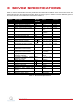
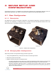
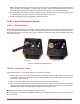


Table Of Contents

6 TESTING AND
TROUBLESHOOTING
This section describes some functional tests to determine if your SRV02 is operating normally. It is assumed that
the SRV02 is connected as described in the Section 5, above. To carry out these tests, it is preferable if the user can
use a software such as QUARC
r
or LabVIEW
r
to read sensor measurements and feed voltages to the motor. See
Reference [4] to learn how to interface the SRV02 with QUARC. Alternatively, these tests can be performed with a
signal generator and an oscilloscope.
6.1 Motor
6.1.1 Testing
Ensure the SRV02 motor is operating correctly by going through this procedure:
1. Apply a voltage to analog output channel #0 of the terminal board using, for example, the QUARC software.
2. The motor gear, component #4 shown in Figure 2.1b, should rotate counter-clockwise when a positive voltage
is applied and clockwise when a negative voltage is applied. Remark that the motor shaft and the load shaft
turn in opposite directions.
6.1.2 Troubleshooting
If the motor is not responding to a voltage signal, go through these steps:
• Verify that the power amplifier is functional. For example when using the Quanser VoltPAQ device, is the green
LED lit?
• Check that the data-acquisition board is functional, e.g. ensure it is properly connected, that the fuse is not
burnt.
• Make sure the voltage is actually reaching the motor terminals (use a voltmeter or oscilloscope).
• If the motor terminals are receiving the signal and the motor is still not turning, your motor might be damaged
and will need to be repaired. Please see Section 7 for information on contacting Quanser for technical support.
6.2 Potentiometer
6.2.1 Testing
Test the SRV02 potentiometer with the following procedure:
1. Using a program such as QUARC, measure the analog input channel #0.
2. The potentiometer should output a positive voltage when the potentiometer gear, component #6 in Figure 2.1b,
is rotated counter-clockwise. The measurement should increase positively towards 5 V until the discontinuity
is reached, at which point the signal abruptly changes to -5 V and begins to increase again.
SRV02 User Manual 20