
User manual


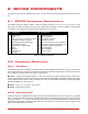


Table Of Contents

Figure 2.2: SRV02 potentiometer wiring
As illustrated in Figure 2.2, the potentiometer is connected to a ±12 V DC power supply through two 7.15 kΩ bias
resistors. Under normal operations, terminal 1 should measure -5 V while terminal 3 should measure 5 V. The actual
position signal is available at terminal 2.
2.2.3 Tachometer
The SRV02-T and SRV02-ET models come equipped with a tachometer that is directly attached to the DC motor
and is depicted with ID #13 in Figure 2.1c. This prevents any latencies in the timing of the response and ensures
that the speed of the motor is accurately measured. Refer to [3] for the tachometer specification sheet.
Figure 2.3: SRV02 tachometer wiring
The motor and tachometer wiring diagram is shown in Figure 2.3. The 4-pin DIN motor connector, component #19,
connects the power amplifier to the positive and negative motor leads. This is the motor input voltage signal that
drives the motor. The 6-pin mini DIN tachometer connector, component #18 shown in Figure 2.1d, is directly wired
to the positive and negative tachometer terminals. This supplies a voltage signal that is proportional to the rotational
speed. The tachometer connector is typically connected to the S3 analog input connector on the power amplifier.
2.2.4 Encoder
The SRV02-E and SRV02-EHR options have an optical encoder installed that measures the angular position of the
load shaft. It is pictured in Figure 2.1c with the label #12. In the SRV02-E system, the encoder used is a US Digital
S1 single-ended optical shaft encoder that offers a high resolution of 4096 counts per revolution in quadrature mode
(1024 lines per revolution). The complete specification sheet of the S1 optical shaft encoder is given in [1].
The encoder in the SRV02-EHR system has a resolution of 8192 counts per revolution in quadrature mode (2042
lines per revolution). Remark that incremental encoders measure the relative angle of the shaft (as opposed to the
SRV02 User Manual
v 1.0