
User manual


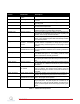
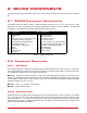


Table Of Contents

potentiometer which measures the absolute angle).
Figure 2.4: SRV02 encoder wiring
The position signal generated by the encoder can be directly connected to the data-acquisition device using a
standard 5-pin DIN cable. The internal wiring of the encoder and the 5-pin DIN connector on the SRV02, component
#17, is illustrated in Figure 2.4.
Caution: Make sure you connect the encoder directly to your data-acquistion device and not to the power
amplifier.
2.3 SRV02-ETS Components
The SRV02-ETS, pictured in Figure 2.5, is an SRV02-ET system with a slip ring mounted on the load gear. This allows
an external load attached on top of the slip ring unit to rotate 360 degrees freely without any cable entanglements.
In addition to the components listed in Table 2.1, Table 2.2 lists some components found on the SRV02-ETS unit
alone.
The components in Table 2.2 are shown and identified in Figure 2.6.
ID Component ID Component
24 Slip ring module chassis 28 Right connector on slip ring
25 Slip ring 29 Left connector on SRV02
26 Slip ring top plate 30 Right connector on SRV02
27 Left connector on slip ring
Table 2.2: Additional components on the SRV02-ETS
2.3.1 Slip Ring Description
The eight-contact slip ring channels the signals attached to the Left and Right connectors on the slip ring, ID #27
and ID #28 depicted in Figure 2.6, to the Left and Right connectors on the SRV02 base, ID #27 and ID #28 shown
in Figure 2.6. This allows the load attached to the load gear atop the slip ring, ID #8, to move freely 360 degrees
without any cable entanglements. This is especially useful, for instance, when used with the inverted rotary pendulum
experiments.
SRV02 User Manual 8