USER GUIDE QuantStudio® 3D Digital PCR System for use with: ® QuantStudio 3D Digital PCR Instrument ™ ® ProFlex 2x Flat PCR System or Dual Flat Block GeneAmp PCR System 9700 ® QuantStudio 3D Digital PCR Master Mix ® QuantStudio 3D Digital PCR 20K Chip ® QuantStudio 3D Digital PCR Chip Loader Catalog Numbers A25581 or A25606 Publication Number MAN0007720 Revision C.0 For Research Use Only. Not for use in diagnostic procedures.
The information in this guide is subject to change without notice. DISCLAIMER LIFE TECHNOLOGIES CORPORATION AND/OR ITS AFFILIATE(S) DISCLAIM ALL WARRANTIES WITH RESPECT TO THIS DOCUMENT, EXPRESSED OR IMPLIED, INCLUDING BUT NOT LIMITED TO THOSE OF MERCHANTABILITY, FITNESS FOR A PARTICULAR PURPOSE, OR NON-INFRINGEMENT.
Contents About this guide . . . . . . . . . . . . . . . . . . . . . . . . . . . . . . . . . . . . . . . . . . . . . . . . . . . . . . . . . . . . 8 Revision history . . . . . . . . . . . . . . . . . . . . . . . . . . . . . . . . . . . . . . . . . . . . . . . . . . . . . . . . . . . . . . . . . 8 Purpose . . . . . . . . . . . . . . . . . . . . . . . . . . . . . . . . . . . . . . . . . . . . . . . . . . . . . . . . . . . . . . . . . . . . . . . 8 Prerequisites . . . . . . . . . . . . . . . . . . . . . . . .
Contents ■ CHAPTER 2 Prepare Samples and Load Reactions . . . . . . . . . . . . . . . . . . 36 Prepare the DNA samples . . . . . . . . . . . . . . . . . . . . . . . . . . . . . . . . . . . . . . . . . . . . . . . . . . . . . . . Quality of DNA . . . . . . . . . . . . . . . . . . . . . . . . . . . . . . . . . . . . . . . . . . . . . . . . . . . . . . . . . . . . . Quantity of DNA . . . . . . . . . . . . . . . . . . . . . . . . . . . . . . . . . . . . . . . . . . . . . . . . . . . . . . . . . . .
Contents ■ CHAPTER 4 Analyze the Prepared Chips . . . . . . . . . . . . . . . . . . . . . . . . . . . . . 66 ® Using the QuantStudio 3D Digital PCR Instrument . . . . . . . . . . . . . . . . . . . . . . . . . . . . . . . . . About imaging and primary analysis . . . . . . . . . . . . . . . . . . . . . . . . . . . . . . . . . . . . . . . . . Analysis workflow . . . . . . . . . . . . . . . . . . . . . . . . . . . . . . . . . . . . . . . . . . . . . . . . . . . . . . . . . About the instrument interface . .
Contents ■ APPENDIX B Networking . . . . . . . . . . . . . . . . . . . . . . . . . . . . . . . . . . . . . . . . . . . . . . 95 Networking overview . . . . . . . . . . . . . . . . . . . . . . . . . . . . . . . . . . . . . . . . . . . . . . . . . . . . . . . . . . . 95 About the network port and wireless adaptor . . . . . . . . . . . . . . . . . . . . . . . . . . . . . . . . . 95 Networking guidelines and best practices . . . . . . . . . . . . . . . . . . . . . . . . . . . . . . . . . . . .
Contents ■ Documentation and support . . . . . . . . . . . . . . . . . . . . . . . . . . . . . . . . . . . . . . . . . . . 121 Customer and technical support . . . . . . . . . . . . . . . . . . . . . . . . . . . . . . . . . . . . . . . . . . . . . . . . 121 Limited product warranty . . . . . . . . . . . . . . . . . . . . . . . . . . . . . . . . . . . . . . . . . . . . . . . . . . . . . .
About this guide CAUTION! ABBREVIATED SAFETY ALERTS. Hazard symbols and hazard types specified in procedures may be abbreviated in this document. For the complete safety information, see the “Safety” appendix in this document. IMPORTANT! Before using this product, read and understand the information in the “Safety” appendix in this document. Revision history Revision Date 01 03, 2013 Initial version 02 06, 2013 Updated general chip preparation and instrument networking. A.
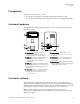
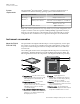
About this guide Prerequisites Prerequisites This guide also assumes that you have: • Knowledge of techniques for handling and preparing samples for PCR. • A general understanding of data storage, file transfers, and copying and pasting. Instrument hardware The QuantStudio® 3D Digital PCR Instrument consists of the components shown in the following figure. 1 8 4 2 5 3 7 6 Touchscreen – Provides access to the instrument functions, such as data transfer and instrument operation.
About this guide Instrument consumables System requirements The QuantStudio® 3D AnalysisSuite™ Software is a web-based application that is verified for use with the following operating systems and internet browsers. Operating system version Microsoft® Windows® 7 Browser version 32-bit, Service Pack 1 Google® Chrome™ v37 64-bit, Service Pack 1 Microsoft® Internet Explorer® v10 and v11 Mozilla® Firefox® v32 Apple® Macintosh® OS X® v10.9.
1 Getting Started ■ ■ ■ ■ ■ About the QuantStudio® 3D Digital PCR System . . . . . . . . . . . . . . . . . . . . . . . . . 11 Operating the instrument . . . . . . . . . . . . . . . . . . . . . . . . . . . . . . . . . . . . . . . . . . . . . . 13 Prepare the QuantStudio® 3D Digital PCR System for use . . . . . . . . . . . . . . . . . 14 Connect the QuantStudio® 3D Instrument to a network . . . . . . . . . . . . . . . . . . . 34 Connect the QuantStudio® 3D AnalysisSuite™ Software . . . . . . . . . . . . .
1 Chapter 1 Getting Started About the QuantStudio® 3D Digital PCR System Data collection The QuantStudio® 3D Digital PCR System collects raw fluorescence data from the QuantStudio® 3D Digital PCR 20K Chip following PCR amplification. The instrument performs a reading of a Digital PCR 20K Chip, which consists of multiple image captures, in the following three phases: 1.
Chapter 1 Getting Started Operating the instrument 1 Operating the instrument Compatible reagent kits and assays The QuantStudio® 3D Digital PCR System can be used to perform experiments using compatible Applied Biosystems® reagent kits and assays. General information on preparing digital PCR reactions is included in this document.
1 Chapter 1 Getting Started Prepare the QuantStudio® 3D Digital PCR System for use Prepare the QuantStudio® 3D Digital PCR System for use About the installation You can install the QuantStudio® 3D Digital PCR System within one hour. The installation requires your participation at all times, so plan to spend most of your time working with the instrument. Note: The time required to install the QuantStudio® 3D System can vary depending on the type of networking solution that you choose.
Chapter 1 Getting Started Prepare the QuantStudio® 3D Digital PCR System for use Plan the laboratory layout Room PCR Setup Work Area (pre-PCR room) 1 When planning the placement of the QuantStudio® 3D Digital PCR System components, give special consideration to the design and organization of the laboratory.
1 Chapter 1 Getting Started Prepare the QuantStudio® 3D Digital PCR System for use Choose the instrument locations Placement of the QuantStudio® 3D Digital PCR Instrument and ProFlex™ 2x Flat PCR System (or Dual Flat Block GeneAmp® PCR System 9700) can greatly affect their performance. For both instruments, select installation locations that satisfy all of their specific environmental requirements.
Chapter 1 Getting Started Prepare the QuantStudio® 3D Digital PCR System for use Install the QuantStudio® 3D Digital PCR Instrument 1 1. Plan the organization of your laboratory.
1 Chapter 1 Getting Started Prepare the QuantStudio® 3D Digital PCR System for use c. Remove the QuantStudio® 3D Instrument from the package and set it on a clean level surface, then remove the protective cover. d. Inspect the QuantStudio® 3D Instrument for damage caused during transportation. If the instrument is damaged, note the location and appearance of the damage, then contact customer support or your service representative for assistance.
Chapter 1 Getting Started Prepare the QuantStudio® 3D Digital PCR System for use 1 6. If you intend to connect your instrument to a network, prepare the physical network connection: IMPORTANT! Connecting the instrument to a network is optional and can be done at a later time if you desire. Connection Wired Wireless Action Connect one end of a standard category-6 Ethernet cable to the RJ-45 port on the back panel of the instrument and the other end to an open network port. 1.
1 Chapter 1 Getting Started Prepare the QuantStudio® 3D Digital PCR System for use 7. Install the QuantStudio® 3D Instrument: a. Connect the power cord to the QuantStudio® 3D Instrument, press the power switch to the ON position, then wait for it to start (about 30 seconds). The QuantStudio® 3D Instrument is ready to configure when the touchscreen displays the End User License Agreement.
Chapter 1 Getting Started Prepare the QuantStudio® 3D Digital PCR System for use 1 d. In the Choose Connection Type screen, select the appropriate connection: Connection Wired Wireless Action Touch LAN, then wait for the instrument to connect to the network. 1. Touch Wireless. 2. In the Available Wireless Network screen, touch the desired wireless hotspot. Note: The signal strength of a wireless hotspot is indicated by the number of bars present in the wireless icon ( ).
1 Chapter 1 Getting Started Prepare the QuantStudio® 3D Digital PCR System for use e. In the Network Complete screen, touch OK. f. In the Configuration screen, touch Edit to change the instrument settings. g. In the Edit Configuration screen, modify the fields as needed, then touch Save. • Touch the Instrument Name field, enter up to a 16-character name for to save the setting.
Chapter 1 Getting Started Prepare the QuantStudio® 3D Digital PCR System for use 1 h. In the Configuration screen, touch OK to accept the instrument configuration. The QuantStudio® 3D Instrument is ready to use when the touchscreen displays the Start Run screen. 8. Open the package and place the QuantStudio® 3D Digital PCR Chip Loader on the surface where you will load Digital PCR 20K Chips. Attach the power cord to the Chip Loader and connect it to an outlet.
1 Chapter 1 Getting Started Prepare the QuantStudio® 3D Digital PCR System for use c. Remove the ProFlex™ PCR System Base Module from the package and set it on a clean, level surface, then remove the protective cover. 15.2 cm (6 in) ProFlex PCR System CAUTION HOT 20 cm (8 in) 1 5 cm (2 in) 2 ProFlex PCR System QuantStudio® 3D Instrument 2 ProFlex™ PCR System 1 IMPORTANT! The ProFlex™ PCR System must be installed on a level surface.
Chapter 1 Getting Started Prepare the QuantStudio® 3D Digital PCR System for use 1 b. While holding the riser in place with one hand, insert the thin end of the cable tie through the opening at the base of the foot. When the end is visible on the other side of the foot, draw the cable tie through and connect the ends to form a loop. c.
1 Chapter 1 Getting Started Prepare the QuantStudio® 3D Digital PCR System for use e. Using the second cable tie, repeat steps a-d to secure the riser at the other end of the foot. a b 45° c d 6. Using scissors, remove the excess material from each cable tie. 4x ProFlex PCR System 7. Carefully roll the ProFlex™ System back onto its feet.
Chapter 1 Getting Started Prepare the QuantStudio® 3D Digital PCR System for use 1 8. Unpack and install the sample block module: a. Open the package containing the sample block module and inspect it for damage caused during transportation. If the module is damaged, note the location and appearance of the damage, then contact customer support for assistance. b. Pull the lever on the rear panel of the ProFlex™ PCR System Base Module away from the unit to its maximum extension.
1 Chapter 1 Getting Started Prepare the QuantStudio® 3D Digital PCR System for use 10. Set up the ProFlex™ System: a. Open the package containing the Chip Adapters and install them. Note: Each Chip Adapter includes a set of four alignment pegs that fit into the holes of a flat sample block. The Chip Adapter can fit onto either side of the sample block (right or left). CAUTION HOT b. Connect the power cord, power on the ProFlex™ System, then wait for it to start (about 45 seconds).
Chapter 1 Getting Started Prepare the QuantStudio® 3D Digital PCR System for use 1 11. For optimal results, create a new method from the existing 3D template supplied with the ProFlex™ System and verify the pre-defined method for thermal cycling the QuantStudio® 3D Digital PCR 20K Chips: Table 1 ProFlex™ 2x Flat PCR System PCR Method PCR Protocol Stage 1 Stage 3 96.0°C 60.0°C 98.0°C 60.0°C 10.0°C[1] 0:10:00 0:02:00 0:00:30 0:02:00 ∞ 1x (Hold) [1] Stage 2 39x (Cycles) Cover Temp.
1 Chapter 1 Getting Started Prepare the QuantStudio® 3D Digital PCR System for use c. Remove the GeneAmp® PCR System 9700 Base Module from the package and set it on a clean level surface, then remove the protective cover. 15.
Chapter 1 Getting Started Prepare the QuantStudio® 3D Digital PCR System for use 1 e. Inspect the Dual Flat Block Module for damage caused during transportation. If the instrument is damaged, note the location and appearance of the damage, then contact customer support for assistance. 3. Set up the GeneAmp® PCR System 9700: a. Open the package containing the QuantStudio® 3D Tilt Base for Dual Flat Block GeneAmp® PCR System 9700 and install it beneath the thermal cycler.
1 Chapter 1 Getting Started Prepare the QuantStudio® 3D Digital PCR System for use d. When the GeneAmp® PCR System 9700 displays the main menu, confirm that the version number displayed on the screen is 3.12 or greater. If the version number is less than 3.12, contact technical support to upgrade the instrument firmware before continuing. IMPORTANT! The GeneAmp® PCR System 9700 must be running firmware version 3.12 or greater to thermal cycle Digital PCR 20K Chips.
Chapter 1 Getting Started Prepare the QuantStudio® 3D Digital PCR System for use 1 b. Press the D/M/Y or Y/M/D soft keys until the format you want for the current date displays in the Date field. c. Use the numeric keys to enter the values into the Day, Month, and Year fields. 8. From the Main menu, create a user: a. From the Main menu, press User (F5). The Select User Name screen displays a list of names of all users who have been added to the instrument displays in a 4 x 5 matrix.
1 Chapter 1 Getting Started Connect the QuantStudio® 3D Instrument to a network If you... Then... do not want to protect your methods press Accept (F1) again. want to protect your methods see the GeneAmp® PCR System 9700 Base Module User Manual (Pub. no. 4303481) for instructions on securing your methods. want to return to the Main menu without adding the new user name press Cancel (F5). 9.
Chapter 1 Getting Started Connect the QuantStudio® 3D AnalysisSuite™ Software 1 Connect the QuantStudio® 3D AnalysisSuite™ Software You can connect to the QuantStudio® 3D AnalysisSuite™ Software before or after you install the QuantStudio® 3D Digital PCR Instrument. The software supports two methods of deployment (cloud and server), so the method that you follow will depend upon the deployment you purchased.
2 Prepare Samples and Load Reactions ■ ■ ■ ■ ■ Prepare the DNA samples . . . . . . . . . . . . . . . . . . . . . . . . . . . . . . . . . . . . . . . . . . . . . 36 Prepare the digital PCR reactions . . . . . . . . . . . . . . . . . . . . . . . . . . . . . . . . . . . . . . . 38 Load the Digital PCR 20K Chips . . . . . . . . . . . . . . . . . . . . . . . . . . . . . . . . . . . . . . . . 40 Load the chips using the Chip Loader . . . . . . . . . . . . . . . . . . . . . . . . . . . . . . . . . .
Chapter 2 Prepare Samples and Load Reactions Prepare the DNA samples 2 Quantitation methods Before performing digital PCR experiments, consider quantifying the amount of gDNA or cDNA in each sample.
2 Chapter 2 Prepare Samples and Load Reactions Prepare the digital PCR reactions Determine the optimal dilution when the target is unknown If the target copy number per genome is unknown, say for a locus of unknown copies per genome or RNA of unknown expression level, we recommend that you determine the optimal dilution by loading and imaging a dilution series of each sample at the expected digital range.
Chapter 2 Prepare Samples and Load Reactions Prepare the digital PCR reactions Prepare the reaction mix and samples 2 In this procedure, you will prepare the PCR reactions for the samples that you intend to load to QuantStudio® 3D Digital PCR 20K Chip. The volumes of the example protocol have been adjusted so that two chips are run for each sample. Table 3 PCR Reaction Mix Volume (μL) Material Stock conc. Per chip 1 sample/ 2 chips[1] Final conc. QuantStudio® 3D Digital PCR Master Mix 2X 7.
2 Chapter 2 Prepare Samples and Load Reactions Load the Digital PCR 20K Chips 4. In a 0.5- or 1.5-mL low-binding reaction tube, prepare sufficient PCR reaction mix for your samples. Prepare the reaction mix at room temperature and scale the component amounts appropriately, depending on the number of samples that you are running. Note: The following example assumes that you will load each sample to two Digital PCR 20K Chips. Volume (μL) Material 1 sample/ 2 chips [1] 10 samples/ 20 chips[1] 17.4 174.
Chapter 2 Prepare Samples and Load Reactions Load the Digital PCR 20K Chips Guidelines for loading and sealing Digital PCR 20K Chips 2 To ensure the proper processing and analysis of your loaded Digital PCR 20K Chip, handle them according to the following guidelines: • Always wear powder-free gloves when loading and sealing Digital PCR 20K Chips. IMPORTANT! Never handle Digital PCR 20K Chips or Chip Case Lids without gloves.
2 Chapter 2 Prepare Samples and Load Reactions Load the chips using the Chip Loader Load the chips using the Chip Loader The following procedure explains how to load QuantStudio® 3D Digital PCR 20K Chips automatically using a QuantStudio® 3D Digital PCR Chip Loader. This procedure assumes that you have prepared your PCR reactions as explained in “Prepare the reaction mix and samples“ on page 39 and are ready to load them onto Digital PCR 20K Chips.
Chapter 2 Prepare Samples and Load Reactions Load the chips using the Chip Loader 2 Recovering from a Chip Loader error Perform the following steps if the QuantStudio® 3D Digital PCR Chip Loader status light flashes red, indicating that it has encountered an error. 1. Power off the Chip Loader, wait 30 seconds, then power it on. 2. If the status light is still flashing red, press the load button and record the sequence of colors displayed. 3.
2 Chapter 2 Prepare Samples and Load Reactions Load the chips using the Chip Loader IMPORTANT! Confirm that the tip is locked firmly in place before proceeding. Keep out of sunlight 4 1 2 3 Plunger UV-Activated Chip Sealant Syringe 3 Chip Sealant Tip (twist to attach) 4 Brown plastic bag (do not discard) 1 2 3. Prepare a syringe containing Immersion Fluid: a. Remove the syringe, plunger, and tip from the packaging. b.
Chapter 2 Prepare Samples and Load Reactions Load the chips using the Chip Loader 2 4. Load the PCR reaction onto a Digital PCR 20K Chip: a. Open the QuantStudio® 3D Digital PCR 20K Chip package, then gently grasp the chip by its sides and load it face-up into the chip nest. Lock the Digital PCR 20K Chip into place by pressing down the chip nest lever ( ) prior to placing the chip into the chip nest as shown ( ).
2 Chapter 2 Prepare Samples and Load Reactions Load the chips using the Chip Loader c. Remove the red protective film from a QuantStudio® 3D Digital PCR Chip Case Lid, press the Lid Nest button ( ), carefully place the Chip Case Lid into the Lid Nest as shown ( ), then release the button to clamp the chip in place. IMPORTANT! Before applying the Chip Case Lid, make certain that it is correctly oriented to the Digital PCR 20K Chip assembly. 2 1 d.
Chapter 2 Prepare Samples and Load Reactions Load the chips using the Chip Loader 2 e. Press the black loading button on the Chip Loader to load the Digital PCR 20K Chip. IMPORTANT! Before pressing the loading button, confirm that the Sample Loading Blade is firmly seated on the loader arm. The status light flashes green during the loading sequence, and displays solid green when finished. f.
2 Chapter 2 Prepare Samples and Load Reactions Load the chips using the Chip Loader 5. Rotate the Chip Loader arm so that the Chip Case Lid solidly contacts the Digital PCR 20K Chip, firmly press down for 15 seconds to ensure a tight seal, then press the Lid Nest button and return the Chip Loader arm to its original position. >15 sec IMPORTANT! While applying the lid: · Press down on the Chip Loader until you reach a hard stop. The arm requires · · >20 lbs of force to apply the Chip Case Lid.
Chapter 2 Prepare Samples and Load Reactions Load the chips using the Chip Loader 2 7. Seal the Chip Case using Chip Sealant: a. Hold the syringe tip just above (or in slight contact with the inside wall) of the fill port of the sealed Chip Case, then carefully fill the port with Chip Sealant, ensuring that the fluid touches the walls of the port. To ensure the seal, create a dome of sealant over the top of the port.
2 Chapter 2 Prepare Samples and Load Reactions Load chips manually c. When the light powers off (approximately ³15 seconds), remove the chip and place it on a clean, dry, lint-free surface. IMPORTANT! Remove the Digital PCR 20K Chip assembly only after the ultraviolet light powers off, indicating that the curing of the Chip Sealant is complete. IMPORTANT! Do not squeeze sealed Digital PCR 20K Chips.
Chapter 2 Prepare Samples and Load Reactions Load chips manually 2 • Immersion Fluid Tip • UV-Activated Chip Sealant Syringe • UV-Curing Stylus for Chip Sealant • UV-Curing Stylus Stand • Isopropanol • Gloves, powder-free, nitrile • Heated block (capable of maintaining 40±1°C) • Scissors • Cleanroom-grade, low-lint polyester wipes • Microcentrifuge • Pipettes and tips, P10 to P1000 • Vortexer Load and seal the Digital PCR 20K Chips WARNING! ULTRAVIOLET LIGHT HAZARD.
2 Chapter 2 Prepare Samples and Load Reactions Load chips manually IMPORTANT! Confirm that the tip is locked firmly in place before proceeding. Keep out of sunlight 4 1 2 3 Plunger UV-Activated Chip Sealant Syringe 3 Chip Sealant Tip (twist to attach) 4 Brown plastic bag (do not discard) 1 2 3. Prepare a syringe containing Immersion Fluid : a. Remove the syringe, plunger, and tip from the packaging. b.
Chapter 2 Prepare Samples and Load Reactions Load chips manually 2 4. Remove the following consumables from their packaging and place them on a clean, dry, lint-free surface: • QuantStudio® 3D Digital PCR Chip Case Lid • QuantStudio® 3D Digital PCR Sample Loading Blade 5. Open the QuantStudio® 3D Digital PCR 20K Chip package, gently grasp the chip by its sides, then place it face-up on the heated block, preheated to 40°C.
2 Chapter 2 Prepare Samples and Load Reactions Load chips manually c. While holding the Sample Loading Blade at a 70-80° angle relative to the heated block so that the port faces up, place the edge of the blade at the end of the Digital PCR 20K Chip. Adjust the angle of the blade until you visually confirm that it is wetting the chip. Then, in one smooth motion, slowly drag the blade across the chip while applying a slight downward pressure to dispense the reaction.
Chapter 2 Prepare Samples and Load Reactions Load chips manually 2 7. Seal the Digital PCR 20K Chip: a. Remove the red protective film from the QuantStudio® 3D Digital PCR Chip Case Lid, then carefully place it onto the prepared Digital PCR 20K Chip so that the window in the lid aligns with the chip. IMPORTANT! Before applying the Chip Case Lid, make certain that it is correctly oriented to the Digital PCR 20K Chip assembly. b.
2 Chapter 2 Prepare Samples and Load Reactions Load chips manually 9. Seal the Chip Case using Chip Sealant: a. Hold the syringe tip just above (or in slight contact with the inside wall) of the fill port of the sealed Chip Case, then carefully fill the port with Chip Sealant, ensuring that the fluid touches the walls of the port. To ensure the seal, create a dome of sealant over the top of the port. IMPORTANT! Apply the Chip Sealant to the fill port only.
Chapter 2 Prepare Samples and Load Reactions Load chips manually 2 10. Visually inspect the sealed Digital PCR 20K Chip for potential problems: • Leaks – Confirm that no Immersion Fluid is leaking from the fill port or around the seal between the Chip Case and lid. • Bubbles – Confirm that the Chip Case is free of excessive bubbles. One small air bubble is acceptable. • Correct lid orientation – Confirm that the Chip Case Lid and the Digital PCR 20K Chip are correctly aligned.
3 Perform the PCR ■ ■ Choosing a thermal cycler . . . . . . . . . . . . . . . . . . . . . . . . . . . . . . . . . . . . . . . . . . . . . 58 Thermal cycle the Digital PCR 20K Chips . . . . . . . . . . . . . . . . . . . . . . . . . . . . . . . .
Chapter 3 Perform the PCR Choosing a thermal cycler Prepare the thermal cycler 3 Before running each batch of Digital PCR 20K Chips, perform the following to ensure efficient thermal cycling: • Confirm that the following parts are installed or available for use: a. Confirm that clean QuantStudio® 3D Digital PCR Thermal Pads are available for use. IMPORTANT! If a QuantStudio® Thermal Pad becomes dirty, clean the pad using a low-lint wipe sprayed with isopropanol, then let it dry.
3 Chapter 3 Perform the PCR Choosing a thermal cycler • Confirm the thermal cycler is running the correct firmware version number to thermal cycle Digital PCR 20K Chips: – ProFlex™ 2x Flat PCR System – The version number displayed in the About Instrument screen must be 1.1.4 or greater. About Instrument Wired IP Address Wireless IP Address 10.0.2.15 Instrument Serial Number Block Serial Number UUID Firmware Version 12345678 12345678 b1765c31bd08370ba632d35ea56c505b 1.1.4 1.1.
Chapter 3 Perform the PCR Thermal cycle the Digital PCR 20K Chips 3 Table 5 GeneAmp® PCR System 9700 PCR Method PCR Protocol Stage 1 Stage 3 96.0°C 60.0°C 98.0°C 60.0°C 10.0°C[1] 10:00 2:00 0:30 2:00 99:59 1x (Hold) [1] Stage 2 39x (Cycles) Run Speed Reaction Volume Standard 20 μL 1x (Hold) Optional step.
3 Chapter 3 Perform the PCR Thermal cycle the Digital PCR 20K Chips Guidelines for handling Chip Cases To ensure the proper function of your loaded Digital PCR 20K Chips, handle the Chip Cases according to the following guidelines: • Always wear powder-free gloves when handling Chip Cases. IMPORTANT! Never handle the Chip Cases without gloves. Oils from your hands can contaminate the Digital PCR 20K Chips and interfere with imaging.
Chapter 3 Perform the PCR Thermal cycle the Digital PCR 20K Chips 3 3. Load the QuantStudio® 3D Digital PCR 20K Chips into the thermal cycler: a. Place the sealed Digital PCR 20K Chips onto the sample block so that the fill ports on the chips are positioned toward the front of the thermal cycler. The fill port must be elevated during thermal cycling to prevent leaks from improperly sealed chips.
3 Chapter 3 Perform the PCR Thermal cycle the Digital PCR 20K Chips 4. Use the thermal cycler to select and start the pre-programmed run for the Digital PCR 20K Chips. See the ProFlex™ PCR System User Guide (Pub. no. MAN0007697) or the GeneAmp® PCR System 9700 Base Module User Manual (Pub. no. 4303481) for more information on running methods. You can remove the Digital PCR 20K Chips from the block immediately after the final extension step at 60°C is complete and the temperature of the block is <25°C.
Chapter 3 Perform the PCR Thermal cycle the Digital PCR 20K Chips 3 3. Remove the Chip Adapters from the thermal cycler sample block and place them on a clean, dry surface. Remove the Digital PCR 20K Chips from the Chip Adapters and allow them to equilibrate to room temperature. Note: To remove a chip from a Chip Adapter, push the Digital PCR 20K Chip from beneath and grasp the edges of the Chip Case, then remove it.
4 Analyze the Prepared Chips ■ ■ ■ ■ Using the QuantStudio® 3D Digital PCR Instrument . . . . . . . . . . . . . . . . . . . . . . 66 Analyze the chips . . . . . . . . . . . . . . . . . . . . . . . . . . . . . . . . . . . . . . . . . . . . . . . . . . . . 69 Analyzing the data . . . . . . . . . . . . . . . . . . . . . . . . . . . . . . . . . . . . . . . . . . . . . . . . . . . 73 Using the QuantStudio® 3D AnalysisSuite™ Software . . . . . . . . . . . . . . . . . . . .
Chapter 4 Analyze the Prepared Chips Using the QuantStudio® 3D Digital PCR Instrument Analysis workflow 4 The following figure shows the workflow for running a single QuantStudio® 3D Digital PCR 20K Chip on the QuantStudio® 3D Digital PCR Instrument. Start q Load the thermal cycled Digital PCR 20K Chip into the QuantStudio® 3D Instrument. q Wait for the instrument to detect and image the chip. q Review the results. q Remove the Digital PCR 20K Chip.
4 Chapter 4 Analyze the Prepared Chips Using the QuantStudio® 3D Digital PCR Instrument About the instrument interface The QuantStudio® 3D Digital PCR Instrument features a simple interface for reading thermal cycled QuantStudio® 3D Digital PCR 20K Chips. 4 5 6 1 2 3 Network status icon – Represents the status of the QuantStudio® 3D Instrument network connection: – Wired (Ethernet) connection • selected; connected to network. • – Wired (Ethernet) connection selected; no connection available.
Chapter 4 Analyze the Prepared Chips Analyze the chips 4 Analyze the chips Materials required The following materials are required to image loaded Digital PCR 20K Chips on the QuantStudio® 3D Digital PCR System.
4 Chapter 4 Analyze the Prepared Chips Analyze the chips 2. (Optional) Enter a prefix to apply to each experiment (.eds) file name: a. From the Main Menu of the QuantStudio® 3D Instrument, touch touch Instrument Settings. , then b. In the Instrument Settings menu, touch File Prefix. c. In the File Prefix screen, touch the Prefix field, then enter up to a 174character prefix for the experiment file name.
Chapter 4 Analyze the Prepared Chips Analyze the chips The touchscreen displays the USB drive icon ( Instrument has mounted the USB drive. 4 ) when the QuantStudio® 3D 2. Open the chip tray and load the Digital PCR 20K Chip face-up into the tray. Confirm that the Digital PCR 20K Chip is correctly aligned within the chip tray, then close it. Note: The chip tray is keyed such that the Digital PCR 20K Chip will only fit in one orientation.
4 Chapter 4 Analyze the Prepared Chips Analyze the chips 3. In the instrument touchscreen, wait for the QuantStudio® 3D Instrument to detect and image the chip. IMPORTANT! Do not open the chip tray or remove the USB drive (if present) while the instrument displays the countdown screen. Doing so will invalidate the image data and require you to repeat the run. Once the instrument detects the chip, it begins processing the chip.
Chapter 4 Analyze the Prepared Chips Analyzing the data 4 5. After reviewing the results of the run, open the chip tray and remove the chip (or remove the USB drive, if present) to close the results screen. If the analysis of the imaging data produced a (red) for either probe (FAM™ or ® VIC dye), visually inspect the chip for problems and read the chip again. Note: If the run fails because the instrument is unable to read the Digital PCR 20K Chip, load the chip again to repeat the reading.
4 Chapter 4 Analyze the Prepared Chips Analyzing the data About the results screen The QuantStudio® 3D Digital PCR Instrument displays a summary of the imaging data after each successful run. For each QuantStudio® 3D Digital PCR 20K Chip imaged, the instrument displays the following information: 1 2 7 3 4 5 6 Chip ID – Displays the ID number of the Digital PCR 20K Chip. If the instrument cannot read the chip ID, the touchscreen displays the date and time of the run.
Chapter 4 Analyze the Prepared Chips Analyzing the data About data quality flags 4 Data quality flags generated and displayed by the software are a measure of the overall chip quality, based on well quality thresholds and other data analysis characteristics. Note: For more information on quality assessment in the software, see the user documentation for the QuantStudio® 3D AnalysisSuite™ Software.
4 Chapter 4 Analyze the Prepared Chips Analyzing the data Transfer the results If a data transfer is unsuccessful, you can use the QuantStudio® 3D Instrument Run History screen to transfer experiment files to a USB drive for manual upload to the QuantStudio® 3D AnalysisSuite™ Software.
Chapter 4 Analyze the Prepared Chips Using the QuantStudio® 3D AnalysisSuite™ Software 4 The Run History screen displays the data transfer status next to each file in the instrument memory: • Pass – The instrument successfully transferred the file to the selected destination. • In Progress – The instrument is either processing the imaging data for the associated file, or transferring the file to the selected destination.
4 Chapter 4 Analyze the Prepared Chips Using the QuantStudio® 3D AnalysisSuite™ Software Access the software from a cloud account When deployed in cloud configuration, the AnalysisSuite™ Software is accessed as a web-based application that can be run using any compatible web browser (see “System requirements“ on page 10). To access the software from a cloud account: 1. Confirm that your computer has a network connection.
5 Troubleshooting Troubleshooting chip images using the Chip View The following table summarizes some of the more common problems that can affect imaging of Digital PCR 20K Chips. In the examples shown below, the conditions triggered a data flag and were diagnosed using the Chip View of the AnalysisSuite™ Software. Observation Possible Cause • Excess PCR reaction was present on the Digital PCR 20K Chip after loading it with the Sample Loading Blade.
5 Chapter 5 Troubleshooting Troubleshooting chip images using the Chip View Observation Possible Cause A bubble was present in the Sample Loading Blade when it was used to apply the PCR reaction to the Digital PCR 20K Chip. Action If possible, use the AnalysisSuite™ Software to filter the low quality data points, or discard the chip and run the sample again. When loading the Sample Loading Blades: • If you are using a manual pipette, pipette to the first stop. • Decrease your pipetting speed.
Chapter 5 Troubleshooting Troubleshooting chip images using the Chip View Observation Possible Cause 5 Action • The Digital PCR 20K Chip leaked during thermal cycling or imaging. If present, remove excess Immersion Fluid from the chip lid and run the chip again. • A large bubble was present in the chip (insufficient Immersion Fluid). If possible, use the AnalysisSuite™ Software to filter the low quality data points. • Excess Immersion Fluid is present on the Chip Case Lid.
5 Chapter 5 Troubleshooting Troubleshooting chip images using the Chip View Observation Possible Cause Chip was not completely covered with Immersion Fluid immediately after loading (while still on the chip loader or heated block) Note: (QuantStudio® 3D Instrument firmware version 1.1 or less) Yellow around the edges is a strong indication of evaporation. Action Add Immersion Fluid as soon as the loading blade is off of the chip. Ensure that entire chip is covered with Immersion Fluid, even the edges.
Chapter 5 Troubleshooting Troubleshooting chip images using the Chip View Observation Possible Cause Condensation may have been present on the Digital PCR 20K Chip during imaging. 5 Action IMPORTANT! Condensation may not be visible on the Digital PCR 20K Chip. • If condensation is not visible – If possible, read the Digital PCR 20K Chip again after it has warmed to room temperature.
5 Chapter 5 Troubleshooting Troubleshooting chip images using the Chip View Observation Possible Cause Action Excess template was loaded onto In the QuantStudio® 3D the chip. AnalysisSuite™ Software, check the copies per reaction and dilute the sample accordingly so that it is within the digital range.
Chapter 5 Troubleshooting Troubleshooting chip images using the Chip View Observation Possible Cause Too much sample was left in loading blade. QuantStudio® 3D Digital PCR System User Guide 5 Action Ensure that you are loading only 14.5 µL of reaction mix into the loading blade.
A Maintenance ■ ■ ■ ■ ■ ■ ■ Cleaning the chip tray and sample block . . . . . . . . . . . . . . . . . . . . . . . . . . . . . . . . 86 Configure the instrument settings . . . . . . . . . . . . . . . . . . . . . . . . . . . . . . . . . . . . . . 88 Returning your QuantStudio® 3D Instrument for service . . . . . . . . . . . . . . . . . . 89 Replace the instrument fuses . . . . . . . . . . . . . . . . . . . . . . . . . . . . . . . . . . . . . . . . . . . 90 Update the instrument firmware . . . . . . . . . .
Appendix A Maintenance Cleaning the chip tray and sample block Clean the chip tray or sample block A CAUTION! PHYSICAL INJURY HAZARD. Do not remove the covers to the QuantStudio® 3D Instrument or thermal cycler. There are no components inside the instruments that you can safely service yourself. If you suspect a problem, contact technical support (see “Customer and technical support“ on page 121). CAUTION! PHYSICAL INJURY HAZARD. During instrument operation, the sample block can be heated to 100°C.
A Appendix A Maintenance Configure the instrument settings Configure the instrument settings After you install the QuantStudio® 3D Digital PCR Instrument, you can configure the instrument settings for your region as explained below. (Optional) Set the instrument name Note: The serial number of the QuantStudio® 3D Instrument is the default instrument name. We recommend that you name the QuantStudio® 3D Instrument uniquely.
Appendix A Maintenance Returning your QuantStudio® 3D Instrument for service Set the date and time A Use this procedure to manually configure the time zone, date, and time settings for your instrument. Note: If connected to a network, the QuantStudio® 3D Instrument will automatically synchronize the date and time settings via Network Time Protocol (NTP). However, you will still need to manually set the instrument time zone. 1. From the Main Menu of the touchscreen, touch Settings.
A Appendix A Maintenance Replace the instrument fuses To return your instrument for service: 1. Contact your local customer care center or technical support group (see “Customer and technical support“ on page 121) to obtain a copy of the Certificate of Instrument Decontamination, a service notification, a service call number, and packaging (if required). 2. Decontaminate the QuantStudio® 3D Instrument.
Appendix A Maintenance Update the instrument firmware Replace the fuses A CAUTION! FIRE HAZARD. For continued protection against the risk of fire, replace fuses only with listed and certified fuses of the same type and rating as those currently in the QuantStudio® 3D Instrument. 1. Power off, then unplug the QuantStudio® 3D Digital PCR Instrument. 2. Using a flat-head screwdriver, pry open the fuse door, and remove the fuse holder. 3. Remove each fuse from its fuse holder and inspect it for damage.
A Appendix A Maintenance Update the instrument firmware Update the firmware 1. Download the firmware update: a. Go to www.lifetechnologies.com/support b. Go to Instrument Management (you will need to log in if not already logged in to our website) and find the link to Software, Patches & Updates on the left side of the Instrument Management dashboard. c. In the Software Downloads page, select QuantStudio® 3D Digital PCR Software from the Digital PCR menu. d.
Appendix A Maintenance Calibrate the touchscreen A Calibrate the touchscreen Calibrate the instrument touchscreen periodically as part of the routine maintenance of your instrument, if you observe a decrease in screen responsiveness over time, or if prompted after updating the instrument firmware. 1. From the Main Menu of the touchscreen, touch Service. , then touch Maintenance & 2. In the Maintenance & Service screen, touch Screen Calibration. 3.
A Appendix A Maintenance View the instrument log 4. (Optional) Export the system log to a USB drive: a. Plug the drive into the USB port on the front of the QuantStudio® 3D Instrument. b. In the Instrument Log screen, touch Export, then wait for the instrument to export the log to a text file on the drive. 5. When you are finished, touch 94 , then touch to return to the Main Menu.
B Networking ■ ■ Networking overview . . . . . . . . . . . . . . . . . . . . . . . . . . . . . . . . . . . . . . . . . . . . . . . . . 95 Connect the instrument to the network . . . . . . . . . . . . . . . . . . . . . . . . . . . . . . . . . . 96 IMPORTANT! This document does not provide adequate detail to integrate the QuantStudio® 3D Instrument into all possible network architectures.
B Appendix B Networking Connect the instrument to the network The wireless dongle sold for use with the QuantStudio® 3D Digital PCR Instrument can be installed to an internal USB port behind the rear panel to enable wireless network connectivity. See the product documentation accompanying the adaptor for the network requirements, specifications, and product details.
Appendix B Networking Connect the instrument to the network Materials required Connection Wired Wireless Required network information B Materials CAT6 Ethernet cable of sufficient length with RJ45 connectors (for a 1000Mbit/s network connection or a CAT5 for a 100Mbit/s connection) SparkLAN WUBR-170GN 802.11n Single-Band Wireless Dongle (PN 4483658) Before beginning the installation, collect from a network administrator your network policy for obtaining IP addresses (DHCP or static IP).
B Appendix B Networking Connect the instrument to the network Connect the QuantStudio® 3D Instrument to a network 1. Prepare the physical connection to the network: Connection Wired Action 1. Power on the QuantStudio® 3D Instrument. 2. Connect one end of a standard category-6 Ethernet cable to the RJ-45 port on the back panel of the instrument and the other end to an open network port. Wireless 1.
Appendix B Networking Connect the instrument to the network B 3. Choose the appropriate option: If connecting your instrument to a… Wired network that supports DHCP Action Network setup is complete. Note: The QuantStudio® 3D Instrument is pre-configured for DHCP operation and automatically joins the network when connected. • Wireless network Go to step 4. • Wired network with specific requirements (such as static IP operation) 4.
B Appendix B Networking Connect the instrument to the network d. If your selected wireless hotspot is secure, enter the required authentication information (user name/password), then touch OK. If connecting your instrument to a network that supports DHCP, network setup is complete. Otherwise, go to the next step to configure the TCP/IP settings for the instrument. 6. Set the internet protocol (TCP/IP) properties for the QuantStudio® 3D Instrument: a. In the Network Setup screen, touch Edit Settings. b.
B Appendix B Networking Connect the instrument to the network c. If you elected to assign a static IP to the instrument, touch the following fields and enter the: • IP Address – Enter the static IP address for the instrument. • Netmask – Enter a subnet mask for the network if applicable. • Gateway – Enter a default gateway for the network if applicable. Note: For each setting, touch the associated field, then enter the setting using the keypad and touch Enter to accept the value. d.
B Appendix B Networking Connect the instrument to the network , then configure the Windows Internet Naming Service (WINS) e. Touch settings: • Windows Domain – Enter the domain name of the WINS server. • WINS Server – Enter the IP addresses for the primary (top) and secondary (bottom) WINS servers. IMPORTANT! WINS may be required if you specify a file server as a data destination.
Appendix B Networking Connect the instrument to the network B to return to the Main 7. In the Network Complete screen, touch OK, then touch Menu. After the instrument has successfully connected to the network, the Network Setup screen displays the details of the network connection. Note: If your wireless hotspot performs MAC filtering, you can obtain the Media Access Control (MAC) address of the QuantStudio® 3D Instrument on the label of the wireless dongle that you installed in step 1.
B Appendix B Networking Connect the instrument to the network 3. In the Edit Destinations screen, touch Add to add a data destination. Note: To edit an existing destination, touch the name of the destination. 4. In the Choose Destination Type screen, touch the desired network destination: • • Cloud – Touch to specify a QuantStudio® 3D AnalysisSuite™ Cloud Software data destination. LAN – Touch to specify a network file server data destination. 5.
B Appendix B Networking Connect the instrument to the network • LAN data destination fields: – Target Name – Enter a name to identify the LAN data destination. Note: The target name appears within the Destination Selection and Export screens.
C Parts and Materials ■ ■ ■ How to order from the website . . . . . . . . . . . . . . . . . . . . . . . . . . . . . . . . . . . . . . . . 106 General-use materials and consumables . . . . . . . . . . . . . . . . . . . . . . . . . . . . . . . . 106 Kits, consumables, and accessories . . . . . . . . . . . . . . . . . . . . . . . . . . . . . . . . . . . . .
Appendix C Parts and Materials Kits, consumables, and accessories Description C Source Reaction tubes, DNase/RNase-free, non-stick or low-binding: 0.5-mL or 1.5-mL Fisher Scientific (Cat. no. 13-864-253 or 13-864-254) or MLS Vortexer MLS Water, DNase-free, sterile-filtered MLS Water, deionized MLS Kits, consumables, and accessories Cat. no.
C Appendix C Parts and Materials Kits, consumables, and accessories Cat. no.
D Specifications and Layout ■ ■ ■ ■ ■ ■ Component dimensions and weights . . . . . . . . . . . . . . . . . . . . . . . . . . . . . . . . . . . 109 QuantStudio® 3D Digital PCR Instrument layout and connections . . . . . . . . . 110 Instrument clearances . . . . . . . . . . . . . . . . . . . . . . . . . . . . . . . . . . . . . . . . . . . . . . . . 110 Electrical specifications . . . . . . . . . . . . . . . . . . . . . . . . . . . . . . . . . . . . . . . . . . . . . . . 111 Environmental requirements . . .
D Appendix D Specifications and Layout QuantStudio® 3D Digital PCR Instrument layout and connections QuantStudio® 3D Digital PCR Instrument layout and connections The QuantStudio® 3D Digital PCR Instrument and the ProFlex™ 2x Flat PCR System (or Dual Flat Block GeneAmp® PCR System 9700) can be placed on separate benches or collocated as shown in the following figure. If you place the units adjacent to one another, provide at least 20 cm (8 inches) clearance between them to allow for heat dissipation.
D Appendix D Specifications and Layout Electrical specifications Electrical specifications WARNING! For safety, the power outlet used for powering the instrument must be accessible at all times. In case of emergency, you must be able to immediately disconnect the main power supply to all the equipment. Allow adequate space between the wall and the equipment so that the power cords can be disconnected in case of emergency.
D Appendix D Specifications and Layout Environmental requirements Environmental requirements Ensure that the installation room is maintained under correct environmental conditions. Condition Acceptable Range Installation site Indoor use only Altitude Located between sea level and 2000 m (6500 ft.
Appendix D Specifications and Layout Network requirements D Network requirements The QuantStudio® 3D Digital PCR Instrument supports IPv4 TCP/IP communication and provides two methods for integrating the device into a local area network (LAN, also see “Materials required“ on page 97): • The fast Ethernet adapter (10/100 Mbps) with a RJ45-type connector on the rear panel of the QuantStudio® 3D Instrument allows you to connect the device directly to a standard network port using a standard Category 6 Ethern
E Safety WARNING! GENERAL SAFETY. Using this product in a manner not specified in the user documentation may result in personal injury or damage to the instrument or device. Ensure that anyone using this product has received instructions in general safety practices for laboratories and the safety information provided in this document.
E Appendix E Safety Symbols on this instrument Symbol English Français Do not dispose of this product in unsorted municipal waste Ne pas éliminer ce produit avec les déchets usuels non soumis au tri sélectif. CAUTION! To minimize negative environmental impact from disposal of electronic waste, do not dispose of electronic waste in unsorted municipal waste.
E Appendix E Safety Safety alerts on this instrument Safety alerts on this instrument Additional text may be used with one of the symbols described above when more specific information is needed to avoid exposure to a hazard. See the following table for safety alerts found on the instrument. English CAUTION! Hazardous chemicals. Read the Safety Data Sheets (SDSs) before handling. CAUTION! Hazardous waste. Refer to SDS(s) and local regulations for handling and disposal.
Appendix E Safety Safety information for instruments not manufactured by Thermo Fisher Scientific E Safety information for instruments not manufactured by Thermo Fisher Scientific Some of the accessories provided as part of the instrument system are not designed or built by Thermo Fisher Scientific. Consult the manufacturer's documentation for the information needed for the safe use of these products. Instrument safety General Electrical CAUTION! Do not remove instrument protective covers.
E Appendix E Safety Safety and electromagnetic compatibility (EMC) standards Cleaning and decontamination CAUTION! Cleaning and Decontamination. Use only the cleaning and decontamination methods specified in the manufacturer's user documentation.
Appendix E Safety Chemical safety Reference Environmental design E Description AS/NZS 2064 Limits and Methods of Measurement of Electromagnetic Disturbance Characteristics of Industrial, Scientific, and Medical (ISM) Radiofrequency Equipment ICES-001, Issue 3 Industrial, Scientific and Medical (ISM) Radio Frequency Generators Reference Description Directive 2002/96/EC European Union “WEEE Directive” – Waste electrical and electronic equipment Chemical safety WARNING! GENERAL CHEMICAL HANDLING.
E Appendix E Safety Biological hazard safety Biological hazard safety WARNING! Potential Biohazard. Depending on the samples used on this instrument, the surface may be considered a biohazard. Use appropriate decontamination methods when working with biohazards. WARNING! BIOHAZARD. Biological samples such as tissues, body fluids, infectious agents, and blood of humans and other animals have the potential to transmit infectious diseases.
Documentation and support Customer and technical support Visit www.lifetechnologies.
For support visit lifetechnologies.com/support or email techsupport@lifetech.com lifetechnologies.