
User Manual
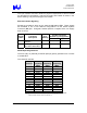

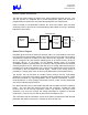
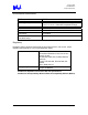

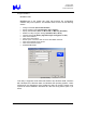
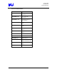
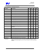
Table Of Contents
- “Trilogy 3” MPCI
- Introduction
- Trilogy 3 Product Overview
- Document Purpose
- Key Features
- What’s Not Supported
- References
- WLAN System Architecture
- WLAN Block Diagram
- WLAN Component Descriptions
- WLAN Transmitter Path
- WLAN Receive Path
- WLAN Microprocessor Control
- WLAN Frequency Generation
- WLAN Hardware Environment
- WLAN Power Requirements
- Modem System Architecture
- Modem Block Diagram
- Modem Hardware Environment
- Modem Power Requirements
- Environmental Performance
- Regulatory
- Ethernet Software Driver and Feature Set
- Modem Software Driver and Feature Set
- Operating System Software Support
- AC’97 Modem Driver Package File Description
- SETUP Usage
- SETUP Customization
- Multilanguage Support
- LTHOMOL.exe (Homologation support utility)
- LTSMMSG.exe (User messaging & system audio support utility)
- Selection of Un-homologated Country Messaging
- Over Current Protection (OCP) Messaging
- System Audio Support
- Quality

Trilogy 3 MPCI
M3AWEB/56GA
Product Specification
The 2-pin modem connector meets the physical requirements of and is located
per the Mini-PCI specification. Antenna connectors are located as shown in the
above drawing. They are Hirose type U.FL-R-SMT.
External Indicator Signaling
Signals are provided to drive up to 2 external LAN Status LEDs. These signals
are available in one of two different configurations via the bottom System
Connector (SC) pins. All signals, whether positive or negative drive, can supply
6mA of current.
System Connector
Pinouts by Configuration
Signal
Name
Functional
Description
Drive
Polarity
Standard Option B
Power Power applied to
Adapter
Positive NA 12+/(No -)
Link
Flashing: Scanning
On Solid: Associated
Negative
11+/13-
NA
WLAN Operating Channels
The FCC (US), IC (Canada), and ETSI (Europe) specify operation from 2.4 GHz
to 2.4835 GHz.
The channels used are:
Channel
Center
Frequency
(MHz)
Start
Frequency
(MHz)
End
Frequency
(MHz)
1 2412 2400 2424
2 2417 2405 2429
3 2422 2410 2434
4 2427 2415 2439
5 2432 2420 2444
6 2437 2425 2449
7 2442 2430 2454
8 2447 2435 2459
9 2452 2440 2464
10 2457 2445 2469
11 2462 2450 2474
12 2467 2455 2479
13 2472 2460 2484
14 2483 2471 2495*
Highlights denote 3 most commonly used (non-overlapping) Ch’s in the U.S.
*Japan specifies 2.483 to 2.495 for Channel 14.
Intel Confidential – Controlled Access
Page 11 of 29