
User Manual
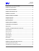
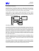
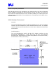
Table Of Contents
- “Trilogy 3” MPCI
- Introduction
- Trilogy 3 Product Overview
- Document Purpose
- Key Features
- What’s Not Supported
- References
- WLAN System Architecture
- WLAN Block Diagram
- WLAN Component Descriptions
- WLAN Transmitter Path
- WLAN Receive Path
- WLAN Microprocessor Control
- WLAN Frequency Generation
- WLAN Hardware Environment
- WLAN Power Requirements
- Modem System Architecture
- Modem Block Diagram
- Modem Hardware Environment
- Modem Power Requirements
- Environmental Performance
- Regulatory
- Ethernet Software Driver and Feature Set
- Modem Software Driver and Feature Set
- Operating System Software Support
- AC’97 Modem Driver Package File Description
- SETUP Usage
- SETUP Customization
- Multilanguage Support
- LTHOMOL.exe (Homologation support utility)
- LTSMMSG.exe (User messaging & system audio support utility)
- Selection of Un-homologated Country Messaging
- Over Current Protection (OCP) Messaging
- System Audio Support
- Quality

Trilogy 3 MPCI
M3AWEB/56GA
Product Specification
WLAN System Architecture
The WLAN section of the adapter consists of a 2.4 GHz radio with direct sequence
transmit and receive circuitry using Intersil 3874A Integrated MAC and Base Band
Processor and ISL3685/HFA3783 Intersil radio chipset. The controller circuitry consists
of the Intersil ISL3874A MAC controller with PCI interface, Flash and SRAM.
Crystal oscillators are used to drive the controller and transmit/receive circuits. Power
control circuits are used to selectively enable radio circuitry. Power on reset is
accomplished via a Maxim 6326 Reset IC, and with resistors to select default
configuration parameters and to put circuits into the off state until the firmware has
enabled the outputs from the controller.
Radio
Prism 2.5 Based
SRAM
ISL3874A
Micro- Controller
FLASH Clock
Mini PCI Host I/F
WLAN Block Diagram
The ISL3874A microcontroller section executes under firmware control to process radio,
timer and host events/operations. This chip executes RISC-type instructions in one clock
using a 3-stage pipeline. The chip supports up to 8 active contexts. Context switching
occurs when higher priority events cause an “instant” switch to the appropriate higher
priority context. Contexts can be configured as “foreground” or “background”, where
foreground contexts always have priority, and background contexts operate in a round-
robin fashion. When there are no eligible contexts, the device consumes very little
power. Up to 64 K words of control store and 8 M bytes of RAM buffers are accessible
by the CPU address registers.
All firmware executes from the control store address space in the SRAM in order to
provide the required throughput for 11 MBPS data rates. The 256 KB SRAM supports
low memory variables and host interface, as well as a linked list of send/receive buffers
and host configuration buffers. The upper half of SRAM is used to store the executable
control store code.
The Host PCI interface accesses memory/registers via the ISL3874A controller;
Command/Status registers and Buffer Access Paths are provided to support a simple,
fast interface mechanism. The radio card includes the Direct Sequence send/receive
circuitry, RF synthesizers, reference oscillator, and power switching circuits.
Intel Confidential – Controlled Access
Page 8 of 29