
User Manual
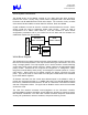
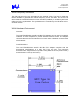
Table Of Contents
- “Trilogy 3” MPCI
- Introduction
- Trilogy 3 Product Overview
- Document Purpose
- Key Features
- What’s Not Supported
- References
- WLAN System Architecture
- WLAN Block Diagram
- WLAN Component Descriptions
- WLAN Transmitter Path
- WLAN Receive Path
- WLAN Microprocessor Control
- WLAN Frequency Generation
- WLAN Hardware Environment
- WLAN Power Requirements
- Modem System Architecture
- Modem Block Diagram
- Modem Hardware Environment
- Modem Power Requirements
- Environmental Performance
- Regulatory
- Ethernet Software Driver and Feature Set
- Modem Software Driver and Feature Set
- Operating System Software Support
- AC’97 Modem Driver Package File Description
- SETUP Usage
- SETUP Customization
- Multilanguage Support
- LTHOMOL.exe (Homologation support utility)
- LTSMMSG.exe (User messaging & system audio support utility)
- Selection of Un-homologated Country Messaging
- Over Current Protection (OCP) Messaging
- System Audio Support
- Quality

Trilogy 3 MPCI
M3AWEB/56GA
Product Specification
WLAN Component Descriptions
The Intel PRO/Wireless 2011B LAN Mini PCI uses the Intersil Corp. Prism 2.5 Chipset to
implement the spreading, modulation, demodulation and de-spreading. The RF up- and
down-conversion approach is the common superhetrodyne architecture with integrated
chip set (ISL3685/HFA3783) manufactured by Intersil. The channel frequency, fc, is
created (transmit) or converted (receive) by mixing with a low side LO frequency, flo, to
the 374 MHz IF (fc= flo + 374 MHz). The 374 MHz IF is converted to/from baseband
using the Intersil I/Q modulator demodulator HFA3783 IC.
WLAN Transmitter Path
The Intersil ISL3874A baseband processor section creates the transmit waveform and
outputs the signal on the TX I/Q lines. The Intersil HFA3783 up-converts the transmit
baseband signal to 374 MHz. To control the side lobes the transmit signal is passed
through a SAW filter (374 MHz center, 22 MHz BW). The signal is then amplified and
mixed up to the channel frequency using Intersil ISL3685 IC. The LO frequency is
lowside (fc – 374M). The signal is then band-pass filtered, amplified, and low-pass
filtered (2.4 to 2.5 GHz passband) to create the required output power while keeping
spurious and harmonic emissions in spec. Two switches are incorporated at the output
to provide for antenna diversity and receive/transmit switching.
WLAN Receive Path
The receive signal passes through the front-end diversity and transmit/receive switches.
The signal is band-pass filtered and then amplified by Intersil ISL3685 and then down-
converted to 374 MHz. The LO frequency is lowside (fc – 374M). The receive signal is
passed through the SAW to provide adjacent channel selectivity. The Intersil HFA3783
creates the baseband I/Q signals and the signal is de-spread and demodulated in the
Intersil ISL3874A.
WLAN Microprocessor Control
The Intersil ISL3874A micro-controller section along with flash and SRAM memory
control the transmitter and receiver. The micro-controller section is derived from the
Intersil HFA3842 and is clocked at 14.67 MHz by a PLL-divided 44 MHz crystal. The
micro-controller along with the embedded firmware runs the 802.11 Media Access
Control (MAC) layer control. The MAC control sends and receives packets and transfers
data to and from the PCI interface to the host computer. The host computer in which the
Mini-PCI is embedded can be a handheld, notebook or fixed computer.
Intel Confidential – Controlled Access
Page 9 of 29