WMA1 PCMCIA Type II Wireless LAN Card User Manual
Federal Communication Commission Interference Statement This equipment has been tested and found to comply with the limits for a Class B digital device, pursuant to Part 15 of the FCC Rules. These limits are designed to provide reasonable protection against harmful interference in a residential installation. This equipment generates, uses and can radiate radio frequency energy and, if not installed and used in accordance with the instructions, may cause harmful interference to radio communications.
Manufacturer's Disclaimer Statement The information in this document is subject to change without notice and does not represent a commitment on the part of the vendor. No warranty or representation, either expressed or implied, is made with respect to the quality, accuracy or fitness for any particular purpose of this document.
1. INTRODUCTION ........................................................................................................................ 5 1.1 Overview ......................................................................................... 5 1.2 Features .......................................................................................... 5 2. DEVICE DESCRIPTION............................................................................................................ 5 2.
1. Introduction 1.1 Overview This user manual describes the feature of the PCMCIA wireless LAN card (model name: WMA1), as well as the physical card installation. WMA1 complies with full IEEE 802.11b standards with bit rate up to 11Mbps and the interface complies with PCMCIA specifications. The WMA1 module can be installed on a variety of gateway (or router) master boards as various wireless gateways (or routers). 1.2 Features * Fully IEEE 802.
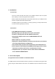
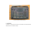
Appearance of the WMA1 card and attached components (bracket and screws) 2.2 Appearance after installed on the Master Board Appearance of the complete WMA1 installation 3.
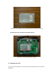
Step 1: Slide the WMA1 PCMCIA Wireless LAN Card Module over the Quanta Gateway master board. Appearance of the WMA1 card and attached components (bracket and screws) Appearance of the Quanta Gateway Master Board Step 2: Directly align the WMA1 card pins to the mapping PCMCIA interface port and then plug-in it.
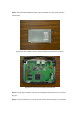
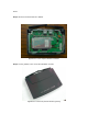
board. Step 4: Mount the external antenna to WMA1. Appearance of the complete WMA1 installation Step 5: Put the gateway cover on and the installation is all set.
View from the bottom of wireless gateway 4. Application The WMA1 as a original WLAN card module can be installed on the Master Board with PCMCIA interface as a Wireless Gateway.
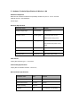
5. Hardware Technical Specification of Wireless LAN Standard Compliance IEEE 802.11b standard and WECA interoperability certified FCC part 15,sec.15. 247/USA CE/ETSI 300.328,300.826/Eurpoe TELEC/Japan Electrical Specification Parameter name Value Remark Supply voltage range 3.0V~3.
Parameter name Value Remark EMI FCC class B ESD 1500V Non-operating Frequency Allocation Regulatory Domain Operating frequency range No. of operating channels North America 2412~2462MHZ 11channel (3 non-overlapping) Europe 2412~2472MHZ 13channel (3 non-overlapping) Japan 2412~2484MHZ 14channels Modulation/Data rate Data Rate Modulation 1M bps DBPSK 2M bps DQPSK 5.
Dynamic Range Parameter name Value Remark Dynamic Range 82 dB Maximum Input level is –5dBm Value Remark System Linearity( (Input) ) Input third order intercept point IIP3 -17 dBm Min. @-28dBm input IIP3 13 dBm Min. @-1dBm input Adjacent Channel Rejection Receive Adjacent Channel Rejection shall be tested with a 25MHz Separation and the desired channel input power is –80dBm. General Specification Value Remark Adjacent channel rejection 35dB.
TX Carrier Suppression 25dB Min. Preamble Length Short/Long Multipath Fading Equalization " 80 ns rms at 11Mbps " 160 ns rms at 5.