BF-01C User Manual Introduction Installing the BF-01C Wireless Connection to the BF-01C Internet Connection Settings Use Overseas Troubleshooting Appendix Thank you for purchasing the BF-01C. This manual describes product installation and its default settings. It also provides troubleshooting information. Please always read this manual before using the product.
1 1 Introduction Main Features This section describes the main product features. • Supports NTT Docomo ”Xi”. (When receiving: Max. 37.5 Mbps; When sending: Max. 12.5 Mbps) ※ The communication speeds are the maximum values in sending and receiving standards. However, these do not indicate actual communication speeds. Data transmission is provided over a best-effort network.
Supported OS (Personal Computers) Windows 7 (32 bit/64 bit), Vista (32 bit/64 bit), XP (32 bit), Mac OS X (10.4/10.5/10.6) ※ Supports Windows 7 Starter/Home Premium/Professional/Ultimate. ※ Supports Windows Vista Home Basic/Home Premium/Business/Ultimate. ※ Windows XP must have Service Pack 3 or later installed. Supported Browsers Internet Explorer 6/7/8/9 Firefox 3.5/3.6/4 Nintendo DS Browser, Nintendo DSi Browser PSP® Internet Browser Internet Explorer Mobile (Windows Mobile 6.
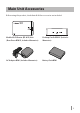
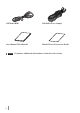
Main Unit Accessories Before using this product, check that all of the accessories are included.
USB Cable BF01 LAN Cable (Free Sample) User Manual (This Manual) Mobile Device Connection Guide Note If separate, additional information is included, refer to that.
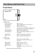
Part Names and Functions Front Panel 1 2 3 1. WIRELESS LED Glowing (light blue) Glowing (purple) Glowing (blue) Glowing (green) Glowing (red) : : : : : Glowing (yellow) Flashing (light blue) Flashing (purple) : : : Flashing (blue) Flashing (green) Off : : : 2.
3. AOSS/DIAG LED Glowing (yellow) : S ecurity key exchange succeeds (AOSS/ WPS succeeds)/Wireless LAN security setting completed Flashing Two Times (blue) : This product can exchange security keys. (LAN Side: AOSS/WPS Idling) (Internet Side: AOSS Idling) *1 Continuous Flashing (blue) : Failed to exchange security keys (AOSS/WPS failed) Flashing (red) : The number of flashes indicates the status of the product.
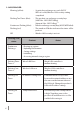
*1 Devices idling with AOSS switch to flashing two times (yellow) when detected by the Internet side of the product. *2 Do not turn off the power when the device is continuously flashing. Doing so can damage it. *3 When the AC adapter is disconnected from the device, turn off the power to it, and remove the battery pack. Return the battery pack to its original position after waiting for a while. Side Panel 4 5 6 7 8 4.
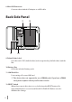
8. Mini USB Connector Connects the included AC adapter or a USB cable. Back Side Panel 9 11 10 12 9. Default Value Label Lists this unit’s SSID (default value) and encryption key (default value) and the like. 10. Battery Box Holds the included battery pack. 11. UIM Card Slot For inserting a Docomo UIM card. ※ This device does not support the use of FOMA cards. If you have a FOMA card, please replace it from your Docomo vendor. 12.
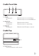
Cradle Front Side 13 14 15 13. LAN LED Glowing (green) Off : : When the wired port is set as the LAN port When the wired port is set as the INTERNET port 14. LINK/ACT LED Glowing (green) Flashing (green) : : When the wired port is linked When the wired port is communicating 15. POWER LED Glowing (green) : When the included AC adapter is connected Cradle Top 16 16. Cradle Connector Connects the main unit's cradle connector.
Cradle Back Side 17 18 19 17. POWER Connector Connects the included AC adapter. 18. Wired Port Switch to operate this as the LAN port or the INTERNET port by using the onoff switch. 19. On-off Switch Switch to use the wired port either as the LAN port or the INTERNET port.
2 2 Installing the BF-01C Power ON/OFF Turn the power ON/OFF using the power button. Power Button When the power is off, hold down the power button for approximately three seconds to turn the power on. When operating this device, hold down the power button for approximately three seconds to turn the power off. Note In the default setting, if no wireless device is connected to the product for approximately one minute, it will automatically switch to standby mode.
3 3 Wireless Connection to the BF-01C Wireless Connection to a Personal Computer This section describes the procedures for connecting this product wirelessly to a personal computer running Windows, using AOSS/WPS (push-button type) as an example. Setting methods vary according to the version of Windows that is running. Note Refer to the Reference Guide for details on other connecting methods. See page 58 in this manual on reference method.
2 When the screen below is displayed, click [Create connection destination]. 3 When the ”User Account Control” screen is displayed, click [Yes] or [Continue].
4 Click the automatic security setting button the screen. 5 When the screen below is displayed, hold down the AOSS button for approximately 2 seconds until the AOSS/DIAG LED flashes. Release the button when the LED flashes. displayed in ※ The product image in the screen is an example. The product and AOSS button position may differ from your system, so check the position of the button in advance.
Hold down the AOSS button until the AOSS/DIAG LED flashes twice in blue. AOSS/DIAG LED 6 The device is automatically detected, and connected. ※ The product image in the screen is an example.
7 Wait for the connection to complete. ※ The product image in the screen is an example. 8 When ”Connection with AOSS completed” or ”Connection with WPS push-button type completed” is displayed, check the name of the connection destination, and click [Save and close]. Note The connection destination name can be freely set.
9 When ”Wireless connection destination creation completed” is displayed, click [Close]. 10 If a screen ”Set Network Location” is displayed, click the location that matches the environment where the devices will be used. (In the example here, click ”Home Network”.
11 If the ”User Account Control” screen is displayed, click [Yes] or [Continue]. 12 If the screen below is displayed, click [Close]. This completes connecting to this product. Note If connecting to this device fails, the AOSS/DIAG LED will continuously flash in blue for approximately 30 minutes, and a screen like the one below is displayed. In such case, click ”Start creating wireless connection from the beginning” and implement the procedures again from step 4 (Page14). ※ Sample screen.
4 4 Troubleshooting Initializing the Settings Use the following procedures to initialize the settings (Reset). 1 Check that the power to the device is on. 2 Remove the back side cover. 3 Hold down the RESET button (for approximately three seconds) until the AOSS/DIAG LED flashes in red. RESET Button 4 After about one minute, check that the AOSS/DIAG LED is lit in yellow. This completes initialization of this product.
5 5 Appendix Product Specifications Main Unit/Cradle Wireless Compliance Interface Standards (LAN Side) Maximum Data Transfer Speed (Theoretical Value) IEEE802.11b / IEEE802.11g / IEEE802.11n ARIB STD-T66 (IEEE802.11b/g) IEEE802.11b 11Mbps IEEE802.11g 54Mbps IEEE802.11n 150Mbps Mode Access Point (AP) Mode Frequency Range 2412 - 2472 MHz 1 - 13 channels No.
Wireless Interface (Internet Side) Compliance Standards IEEE802.11a / IEEE802.11b / IEEE802.11g / IEEE802.11n ARIB STD-T71 (IEEE802.11a) ARIB STD-T66 (IEEE802.11b/g) Maximum Data Transfer Speed (Theoretical Value) IEEE802.11a 54Mbps IEEE802.11b 11Mbps IEEE802.11g 54Mbps IEEE802.11n 150Mbps * IEEE802.11a cannot be used when the device is set for international roaming.
Mobile Interface Compliance Standards LTE (Cat.3) / W-CDMA (R99) / HSDPA (Cat.8) / HSUPA (Cat.6) Maximum Data Transfer Speed (Theoretical Value) LTE 75Mbps W-CDMA 384kbps HSDPA 7.2Mbps HSUPA 5.7Mbps * LTE cannot be used when the device is set for international roaming.
Continuous When Communi- Communicating cation Time When in LTE Communication Approximately 4 Hours When in 3G communication Approximately 6 Hours * Operating times vary according to the environment of use. When in Standby Approximately 30 Hours * Operating times vary according to the environment of use.
Export Administration Regulations This product and its accessories may be subject to Japan's Export Administration Regulations (Foreign Exchange and Foreign Trade Control Law). It also may be subject to American Re-exporting Regulations (Export Administration Regulations). To export or re-export this product and its accessories, use the necessary procedures at your own responsibility and cost. For details on procedures, please contact the Ministry of Economy, Trade and Industry or the U.S.
• Reorient or relocate the receiving antenna. • Increase the separation between the equipment and receiver. • Connect the equipment into an outlet on a circuit different from that to which the receiver is connected. • Consult the dealer or an experienced radio/TV technician for help. This device complies with Part 15 of the FCC Rules.
CE Marking This device has been tested to and conforms to the regulatory requirements of the European Union and has attained CE Marking. The CE Mark is a conformity marking consisting of the letters ”CE”. The CE Mark applies to products regulated by certain European health, safety and environmental protection legislation. The CE Mark is obligatory for products it applies to: the manufacturer affixes the marking in order to be allowed to sell his product in the European market.