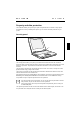
The modem can be operated in the following countries: Multifrequency (MFC) dialling Belgium, Denmark, Germany, Finland, France, Greece, Great Britain, Holland, Ireland, Iceland, Italy, Luxembourg, Norway, Austria, Portugal, Sweden, Switzerland and Spain. Pulse dialling: Belgium, France, Holland and Italy. Also in: Poland, Slovenia, South Africa and Hungary. Connecting notebook modem to telephone connection 3 1 2 Ê Ê Ê Connect the modem cable supplied to the country-specific telephone adapter (1).
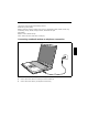
錯誤! 尚未定義樣式。 錯誤! 尚未定義樣式。 PC cards Two PC card slots enable the notebook to operate two type II PC cards or one type III PC card (CardBus or PCMCIA) . ! Consult the documentation supplied by the PC card's manufacturer and follow the instructions provided. Never use force when inserting or removing a PC card. Make sure that foreign objects do not fall into the PC card slot. Installing a PC card Ê Insert the PC card, contacts first, into the lower slot guide.
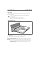
錯誤! 尚未定義樣式。 錯誤! 尚未定義樣式。 Removing a PC card 2 1 Ê Press the eject button (1). It will project further out of the notebook's case. If the eject buttons are pushed in flush with the notebook casing, they must first be snapped out. Press the eject buttons until they snap out. Ê Slide the PC card out of the notebook (2). SmartCards The SmartCard slot enables the notebook to operate one SmartCard. ! Consult the documentation supplied by the SmartCard's manufacturer and follow the instructions provided.
錯誤! 尚未定義樣式。 錯誤! 尚未定義樣式。 Inserting a SmartCard Ê Insert the SmartCard, contacts first, into the lower slot guide. The labelled side of the SmartCard must be facing upward. Ê Gently push the SmartCard into the slot until you feel it click into place. i Consult the documentation supplied with the SmartCard for information on how to install the necessary device drivers. For further information refer to the information files (e.g. *.TXT, *.DOC, *.WRI or *.
錯誤! 尚未定義樣式。 錯誤! 尚未定義樣式。 Pulling out a SmartCard 2 1 Ê Press the eject button (1). It will project further out of the notebook's case. If the eject buttons are pushed in flush with the notebook casing, they must first be snapped out. Press the eject buttons until they snap out. Ê Slide the SmartCard out of its location (2).
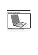
錯誤! 尚未定義樣式。 錯誤! 尚未定義樣式。 Microphone and loudspeakers 1 2 a = built-in microphone b = built-in loudspeakers Your notebook contains a built-in microphone (a) and two loudspeakers (b). If you attach an external microphone, the built-in microphone is disabled. The internal loudspeakers switch off when you attach headphones or external loudspeakers to the audio jack.
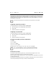
錯誤! 尚未定義樣式。 錯誤! 尚未定義樣式。 Fingerprint ??? The notebook is equipped with a fingerprint reader. Instead of entering a user password, you can also log on to the system with a fingerprint. Before you can use the fingerprint reader, you must install the driver provided on the CD. Bluetooth Keyboard Product Specification Product Bluetooth Keyboard Radio Specification [1] Frequency range: 2.402 – 2.480 GHZ [2] RF output Power: Class 3 [3] Receiver Sensitivity: -70dBm at 0.
錯誤! 尚未定義樣式。 錯誤! 尚未定義樣式。 Automatically re-connect keyboard with notebook PC [5] Intended use/purpose of the equipment Batter life: 24 hour (20,000 times key press) Notebook with detachable K/B which can wireless communicate Notebook Type of modulation GFSK Channel spacing 1Mhz Designation of emission ETSI 300 328 ETSI 300 826 Transmit RF power or power range -6 dBm ~ 0dBm Duty cycle 625us Channel access protocol TDMA Duplex direction Duplex Antenna Type Micro Strip ANT Peak Gain > 3dBi, <-5
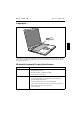
錯誤! 尚未定義樣式。 錯誤! 尚未定義樣式。 Property and data protection Your notebook enables you to protect your system and personal data in a number of ways against unauthorised access. By combining these options, you can achieve maximum protection for your system. Security panel a a = Security panel The security panel enables you to protect your notebook from unauthorised use with a hardware password. When a Security Panel password is activated, the notebook will not start without the correct insertion of a password.
錯誤! 尚未定義樣式。 錯誤! 尚未定義樣式。 No passwords are assigned when the notebook is delivered. The passwords can be assigned with the FJSECS.EXE (supervisor password) and FJSECU.EXE (user password) programmes. The supervisor password and the user password can be assigned with up to 4 key entries. Multiple keys (1+2) can be used together as one key entry. i The supervisor password has to be set before the user password can be assigned.
錯誤! 尚未定義樣式。 錯誤! 尚未定義樣式。 Security functions under Windows Under Windows you can activate a screen saver and protect it with a password. Only those users who know the password can deactivate the screen saver and access any open files. BIOS Setup security functions The Security menu in BIOS Setup offers you various options for protecting your personal data against unauthorised access. By combining these options, you can achieve maximum protection for your system.
錯誤! 尚未定義樣式。 錯誤! 尚未定義樣式。 To set or change a password, proceed as follows: Ê Call BIOS Setup and select the Security menu (see chapter "Settings in BIOS Setup"). You must additionally change into the Hard Disk Security submenu for the hard disk passwords. Ê Mark the Set Supervisor Password or Set User Password field and press the Enter key. You are asked to enter a password: Enter new Password: Ê Enter the password and press the Enter key.
錯誤! 尚未定義樣式。 Ê 錯誤! 尚未定義樣式。 Select the option Exit Saving Changes in the Exit menu. The notebook is rebooted and the password is cancelled. Access protection with SICRYPT PC Lock With SICRYPT PC Lock you can protect your system from unauthorised booting. Then a system can only be booted when the user inserts a valid SmartCard in the SmartCard reader and enters his/her personal code number (PIN).
錯誤! 尚未定義樣式。 錯誤! 尚未定義樣式。 PC Lock permissions You can initialise a SmartCard with one of the following permissions: System The system starts following entry of the user PIN. You can change the user PIN. Setup You can open and change the BIOS Setup and change the user PIN. System+Setup The system starts following entry of the user PIN. You can open and change the BIOS Setup and change the user PIN. Admin The system starts following entry of the user PIN.
錯誤! 尚未定義樣式。 錯誤! 尚未定義樣式。 You can protect your notebook from theft with the Kensington Lock device (a) and a Kensington MicroSaver.
Connecting external devices ! 來源。 Under all circumstances, please observe the safety notes provided in the " " chapter. 錯誤! 找不到參照 Read the documentation on the external device before connecting it. Do not connect or disconnect cables during a thunderstorm. Do not pull on the cable when disconnecting a cable. Always take hold of the actual plug.
錯誤! 尚未定義樣式。 錯誤! 尚未定義樣式。 Line In Connections on the left side IR LAN Connections on the right side
錯誤! 尚未定義樣式。 錯誤! 尚未定義樣式。 The ports are marked with the following symbols (or with similar symbols): LAN LAN-port (Local Area Network, for Network connection) i Port for power adapter PS/2 port (for keyboard or mouse) Headphones port Parallel port Microphone connector Monitor port TV DC In IR Infrared port TV out socket (video output) USB port Serial port Modem connector Some of the external devices require special drivers (see the operating system and external device documentation).
錯誤! 尚未定義樣式。 錯誤! 尚未定義樣式。 Connecting an external keyboard You do not need to switch off your notebook. Ê Simply connect the external keyboard to the PS/2 port on your notebook. Connecting an external PS/2 mouse You do not need to switch off your notebook. Ê Simply connect the mouse to the PS/2 port on your notebook. Connecting a serial mouse Ê Ê Ê Ê Switch off the notebook. Ê Ê Select the correct mouse type. Connect the mouse to the parallel port on your notebook. Switch the notebook on.
錯誤! 尚未定義樣式。 錯誤! 尚未定義樣式。 Establishing an infrared connection Using the infrared software for Windows, you can communicate with another PC or printer equipped with an infrared interface. i Before you can establish an infrared connection, you must have activated the infrared software. Additional information on the infrared interface is contained in the Windows help in the Start menu under the topic "Infrared".
錯誤! 尚未定義樣式。 錯誤! 尚未定義樣式。 Connections for external devices on the Port Replicator II-L The ports for external devices are on the rear of the port replicator II-L. The standard ports are indicated by symbols. i i The LAN connection on the Port Replicator II-L only functions when your notebook is equipped with an internal LAN or modem/LAN module. Otherwise this connection is inoperative. The serial, parallel and audio ports can be configured in the BIOS Setup of the notebook.
錯誤! 尚未定義樣式。 1= 2= 3= 4= Eject button*) Platform release lever Docking port Device-specific platform (Tray F) 錯誤! 尚未定義樣式。 5 = Kensington Lock 6 = Manual eject lever 7 = Indicators*) *) has no function on this LIFEBOOK C-Serie Indicators on the II-L port replicator i The indicators and the eject button on the front of the Port Replicator II-L are covered by the device platform of this LIFEBOOK C-Serie, and are therefore inoperative.
錯誤! 尚未定義樣式。 錯誤! 尚未定義樣式。 Removing the Tray Ê Ê Push the release (1) in the direction of the arrow until the Tray is released on both sides. Remove the Tray (2). Docking the notebook Docking notebook while running If an operating system is installed on your notebook that supports "Plug & Play" and "hot docking" (e.g. Windows 98), you need not switch off the notebook for docking. The notebook may also be in an energy-saving mode.
錯誤! 尚未定義樣式。 Ê 錯誤! 尚未定義樣式。 Place your notebook on the docking device and push it evenly in the direction of the arrows until you feel it engage. Docking a notebook while switched off ! The power adapter cable may not be connected to the DC socket (DC IN) of the notebook when you dock the notebook. The notebook must be in the battery mode. Ê Ê Ê Ê Ê Put your docking device into operation (see documentation for the docking devices).
錯誤! 尚未定義樣式。 錯誤! 尚未定義樣式。 Switching on docked notebook Ê Press the Suspend/Resume button of the notebook. or Ê Press the Suspend/Resume button on the left-hand side of the docking device. Undocking the notebook Undocking notebook while running If an operating system is installed on your notebook that supports "Plug & Play" and "hot docking" (e.g. Windows 98), you need not switch off the notebook for undocking. The notebook may also be in an energy-saving mode.
Settings in BIOS Setup In BIOS Setup you can set the system functions and the hardware configuration of the notebook. The settings can only be changed via the keyboard. When it is delivered, the notebook is set to factory default settings. You can change these settings in BIOS Setup. Any changes you make take effect as soon as you save and quit the BIOS Setup.
錯誤! 尚未定義樣式。 Exiting BIOS Setup To exit BIOS Setup, select the Exit menu from the menu bar. You can then decide which settings you want to save. The Exit menu offers the following options. You must mark the required option and activate it with the Enter key. Exit Saving Changes Select Exit Saving Changes and Yes to save the current settings and exit the BIOS Setup. The device is rebooted and the new settings come into effect.
Troubleshooting and tips ! Take note of the hints in the chapter "Connecting external devices", when you connect or disconnect cables. If a fault occurs in your notebook, try to eliminate it with the measures described in this chapter. If you fail to correct the problem, proceed as follows: Ê Make a note of the steps and the circumstances that led to the fault. Also make a note of any error messages displayed. Ê Ê Switch off the notebook. Contact your sales outlet or our Hotline/Help Desk.
錯誤! 尚未定義樣式。 Ê Start the Setup programme on the CD. You must then reinstall all the drivers. Use the "Drivers & Utilities" CD. The notebook's date or time is incorrect Ê Double-click on the clock in the task bar and adjust the time. or Ê Set the time and/or date in the BIOS Setup menu Main. i If the date and time are repeatedly incorrect when you switch on the notebook, the buffer battery that supplies the internal clock is dead.
錯誤! 尚未定義樣式。 The external monitor stays blank If your screen remains blank this may be due to the following: Monitor is switched off Ê Switch the external monitor on. Power saving has been activated (screen is blank) Ê Press any key to continue. Brightness is set too dark Ê Adjust the brightness of the monitor. Screen output is set to the notebook’s LCD screen Ê Press the key combination [Fn] + [F10] (selecting internal/external display).
錯誤! 尚未定義樣式。 The notebook cannot be started If the notebook does not start after switch on, this may be due to one of the following: The battery is not installed correctly Ê Ê Ê Switch off the notebook. Check whether the battery is installed correctly in its compartment. Switch the notebook on. The battery is dead Ê Charge the battery. Or Ê Install a charged battery. Or Ê Connect the power adapter to the notebook. The power adapter is not connected correctly Ê Ê Ê Switch off the notebook.
錯誤! 尚未定義樣式。 The mouse does not work If the connected mouse does not work, the following can cause it: Incorrect setting in BIOS Setup Ê Check the setting Hotplug in the BIOS Setup in the menu Advanced - Keyboard/Mouse Features. The setting must be set to Enabled. Touchpad driver is not installed properly Ê Ê Deinstall the touchpad driver. Install the actual driver from the "Drivers & Utilities" CD.
錯誤! 尚未定義樣式。 Acoustic warnings A beep sounds every few seconds The battery is almost flat. Ê Charge the battery. Error messages on the screen This section describes the error messages generated by the BIOS-Setup. Error messages displayed by the operating system or programmes are described in the relevant manuals. CMOS Battery Bad If the error message occurs repeatedly, then the buffer battery in the notebook is flat. Ê Connect the notebook via its power adapter to the mains outlet.
錯誤! 尚未定義樣式。 Diskette drive A error Ê Start the BIOS Setup and make sure that the parametre for floppy disk drive A has been set to the format 1.44 Mbyte, 3 1/2 inch. Extended memory failed at offset: xxxx Failing Bits: zzzz zzzz When testing the extended memory an error has resulted at the address xxxx. Ê Check whether the additional memory module has been inserted correctly. Should you receive this error message again, please contact your dealer.
錯誤! 尚未定義樣式。 Press to resume, to SETUP. This error message appears if an error occurs during the self-test before starting the operating system. Ê Ê Press the [F1] function key to start the operating system. Enter the BIOS Setup programme by pressing [F2]. Previous boot incomplete - Default configuration used Due to an error during the previous system boot, default values were used for certain settings. Check the BIOS Setup and the settings.
Memory extension ! The notebook must be switched off when installing/removing the memory modules and may not be in the Suspend mode. So that the current data can be saved in the Save to Disk suspend mode, sufficient memory space must be available on the hard disk (at least the size of the main memory +16 Mbytes).
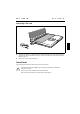
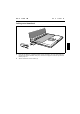
錯誤! 尚未定義樣式。 Installing memory modules 1 2 3 1 Ê Ê Ê Carefully push the two mounting clips outwards (1). Insert the memory module, contacts first, into the slot (2). Carefully push the memory module downwards until you feel it latch into place (3). Removing memory modules 1 3 2 Ê 1 Carefully push the two mounting clips outwards (1). The memory module will flap upward (2). Ê Pull the memory module out of its slot (3).
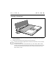
錯誤! 尚未定義樣式。 Mounting the cover 3 Ê Ê Place the cover on its mounting location (1). Ê Fasten the cover with the screw (3). 1 Close the cover on the bottom of the notebook (2). 2 Ê Ê Ê Refit the battery. Place the notebook right side up on a flat, stabile, nonslip surface. Reconnect the cables.
Technical data Notebook Processor µPGA2 (Socket Mount) Intel Pentium III 700 MHz to 1 GHz Intel 815 EM Chipset: Main memory: Maximum 1 Gbyte PC 133 SO DIMM 2 slots for 512 Mbyte modules JEDEC 144 pin Possible modules: • • • • • • CD-ROM drive, 24X speed DVD drive, 8/20X speed (CD-ROM) CD-RW drive, 24/4/8X speed Floppy disk drive Hard disk drive Battery Electrical data Regulations complied with: CE, EN60950, FCC Part 15 Class B, GS, Energy Star, SITO Protection class: II Maximum power draw: (noteb
錯誤! 尚未定義樣式。 錯誤! 尚未定義樣式。 Modem (Mini PCI modem) Integrated modem: 56K, V.90, MC97 Codec, RI LAN connector: Ethernet 10/100T, PME, AOL 2.
錯誤! 尚未定義樣式。 錯誤! 尚未定義樣式。 Charging time (when not in operation): approx. 2 hours Operating time with a battery: approx. 3 hours (without power management) Power adapter Primary • Rated voltage: • • 50 Hz to 60 Hz (automatic) Max. rated current: 1,5 A Secondary Rated voltage: • • 90 V to 240 V (automatic) Frequency: Max. rated current: 19 V 3,16 A You can readily order an additional power adapter and an additional power cable.
Index