English 48 2 Customizing my computer IEEE 1394 port The computer's IEEE 1394 port allows you to connect to an IEEE 1394 supported devices like a video camera or digital camera. See your video or digital camera's documentation for details. PC Card slot The type II CardBus PC Card slot found on the left side of the computer accepts credit-card-sized cards that enhance the usability and expandability of the computer. These cards should have a PC Card logo on them.
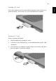
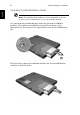
49 Inserting a PC Card Ejecting a PC Card Before ejecting a PC Card: 1 Exit the application using the card. 2 Left-click on the PC Card icon on the taskbar and stop the card operation. 3 Press the slot eject button to pop out the eject button (a); then press it again to eject the card (b). English Insert the card into the slot and make the proper connections (e.g., network cable), if necessary. See your card manual for details.
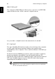
English 50 2 Customizing my computer Port expansion devices Two types of expansion devices are available for your computer: • I/O replicator - adds serial port and parallel port connections to your computer. • EasyPort - adds a host of ports for your computer, and allows you to connect and disconnect peripherals from your computer in one quick step. See your dealer for more information. Upgrade options Your computer delivers superior power and performance.
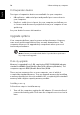
51 Remove the screws from the memory cover (a); then lift up and remove the memory cover (b). 3 Insert the memory module diagonally into the slot (a), then gently press it down (b) until it clicks into place. 4 Replace the memory cover and secure it with the screw. 5 Reinstall the battery pack, and reconnect the AC adapter. 6 Turn on the computer. The computer automatically detects and reconfigures the total memory size.
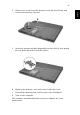
English 52 2 Customizing my computer Swapping AcerMedia drive modules Note: The hard disk drive module is not hot-swappable. You have to turn off your computer before you can swap the module. You can swap the AcerMedia drive with any optional AcerMedia modules. First slide the AcerMedia release latch as shown in the illustration (a). Then remove the optical drive from the AcerMedia bay (b). Then insert the optional AcerMedia module into the AcerMedia bay until the it click into place.
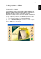
53 Notebook Manager The computer has a built-in system setup program called Notebook Manager. The Windows-based Notebook Manager allows you to set passwords, the startup sequence of the drives, and power management settings. It also shows current hardware configurations. To start the Notebook Manager, press Fn-F2 or follow these steps: 1 Click on Start, Programs, then Notebook Manager. 2 Select the Notebook Manager application to run the program. Click on Help for more information.
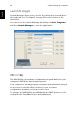
English 54 2 Customizing my computer Launch Manager Launch Manager allows you to set the five launch keys located above the keyboard. See “Touchpad” on page 22 for the location of the launch key. You can access the Launch Manager by clicking on Start, Programs, and then Launch Manager to start the application. BIOS Utility The BIOS Utility is a hardware configuration program built into your computer’s BIOS (basic input/output system).
3 Troubleshooting my computer
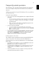
This chapter instructs you on how to deal with common system problems. Read it before calling a technician if a problem occurs. Solutions to more serious problems require opening up the computer. Do not attempt to open the computer by yourself. Contact your dealer or an authorized service center for assistance. key link: www.acersupport.
57 The following is a list of possible situations that may arise during the use of your computer. Easy answers and solutions are provided for each one. I slid the power switch and opened the display, but the computer does not start or boot-up. Look at the Power indicator: • • If it is not lit, no power is being applied to the computer. Check the following: • If you are running on battery power, it may be low and unable to power the computer. Connect the AC adapter to recharge the battery pack.
58 3 Troubleshooting my computer English Image is not full-screen. The computer display has a native resolution of 1024 x 768 (XGA) for the 14.1” and 1400 x 1050 (SXGA+) for the 15.0”. If you set the resolution lower than this, the screen expands to fill the computer display. Right-click on your Windows desktop and select Properties to bring up the Display Properties dialog box. Then click on the Settings tab to make sure that the resolution is set to the appropriate resolution.
59 The keyboard does not respond. The infrared port does not work. Check the following: • Make sure that the infrared ports of the two devices are facing each other (+/- 15 degrees) a maximum of 1 meter apart. • Make sure there is a clear path between the two infrared ports. Nothing should be blocking the ports. • Make sure you have the appropriate software running on both devices (for file transfers) or you have the appropriate drivers (for printing to an infrared printer).
English 60 3 Troubleshooting my computer Troubleshooting tips This notebook computer incorporates an advanced design that delivers onscreen error message reports to help you solve problems. If the system reports an error message or an error symptom occurs, see “Error messages” on page 61. If the problem cannot be resolved, contact your dealer. See “Requesting service” on page 62.
61 If you receive an error message, note the message and take the corrective action. The following table lists the error messages in alphabetical order together with the recommended course of action. Error Messages Corrective Action CMOS Battery Bad Contact your dealer or an authorized service center. CMOS Checksum Error Contact your dealer or an authorized service center. Disk Boot Failure Insert a system (bootable) diskette into the floppy drive (A:), then press Enter to reboot.
English 62 3 Troubleshooting my computer Requesting service International Traveler’s Warranty (ITW) Your computer is backed by an International Traveler’s Warranty (ITW) that gives you security and peace of mind when traveling. Our worldwide network of service centers are there to give you a helping hand. An ITW passport comes with your computer. This passport contains all you need to know about the ITW program. A list of available, authorized service centers is in this handy booklet.
63 You are required to provide the following information: Address:______________________________________ ______________________________________________ Telephone number:____________________________ Machine and model type:_______________________ Serial number:_________________________________ Date of purchase:______________________________ English Name:________________________________________
English 64 3 Troubleshooting my computer
Appendix A Specifications
This appendix lists the general specifications of your computer.
67 Microprocessor Intel® Pentium® M Processor with 1024 KB level 2 cache featuring the new Enhanced Intel® SpeedStep™ technology Memory • Main memory expandable to 2 GB • Dual 200-pin soDIMM sockets • PC2100 DDR-SDRAM (Double Data Rate-Synchronous Dynamic Random Access Memory) support • 512 KB Flash ROM BIOS Data storage • One high-capacity, Enhanced-IDE hard disk • One 5.
68 English • Appendix A Specifications Ergonomically-centered touchpad pointing device with 4-way scroll button I/O ports • One type II CardBus PC Card slot • One RJ-45 jack (Ethernet 10/100) • One RJ-11 phone jack (V.90/V.92) • One DC-in jack • One parallel port (ECP/EPP) • One external monitor port • One speaker/headphone-out jack (3.5mm mini jack) • One audio line-in jack (3.5mm mini jack) • Four (4) USB 2.
69 • Microsoft® Windows® operating system English Power • • Battery pack • 65 wh Li-Ion battery pack • 1.5-hour rapid charge / 3.
English 70 Appendix A Specifications
Appendix B Notices
This appendix lists the general notices of your computer.
73 This device has been tested and found to comply with the limits for a Class B digital device pursuant to Part 15 of the FCC Rules. These limits are designed to provide reasonable protection against harmful interference in a residential installation. This device generates, uses, and can radiate radio frequency energy and, if not installed and used in accordance with the instructions, may cause harmful interference to radio communications.
English 74 Appendix B Notices Notice: Canadian users This Class B digital apparatus meets all requirements of the Canadian Interference-Causing Equipment Regulations. Remarque à l’intention des utilisateurs canadiens Cet appareil numérique de la classe B respected toutes les exigences du Règlement sur le matériel brouilleur du Canada. Modem notices FCC This equipment complies with Part 68 of the FCC rules.
75 Read these instructions carefully. Save these instructions for future reference. 1 Follow all warnings and instructions marked on the product. 2 Unplug this product from the wall outlet before cleaning. Do not use liquid cleaners or aerosol cleaners. Use a damp cloth for cleaning. 3 Do not use this product near water. 4 Do not place this product on an unstable cart, stand, or table. The product may fall, causing serious damage to the product.
76 Appendix B Notices English controls may result in damage and will often require extensive work by a qualified technician to restore the product to normal condition. e If the product has been dropped or the cabinet has been damaged f If the product exhibits a distinct change in performance, indicating a need for service. 12 Replace the battery with the same type as the product's battery we recommend. Use of another battery may present a risk of fire or explosion.
77 CAUTION Danger of explosion if battery is incorrectly replaced. Replace only with the same or equivalent type recommended by the manufacturer. Dispose of used batteries according to local regulations. Recycle if at all possible. ADVARSEL! Lithiumbatteri - Eksplosionsfare ved fejlagtig håndtering. Udskiftning må kun ske med batteri af samme fabrikat og type. Léver det brugte batteri tilbage til leverandøren. ADVARSEL Eksplosjonsfare ved feilaktig skifte av batteri.
78 Appendix B Notices English Apparatus Claims of U.S. Patent Nos. 4,631,603, 4,577,216, 4,819,098, and 4,907,093 licensed for limited viewing uses only. A-Tick notice For safety reasons, only connect headsets with a telecommunications compliance label. This includes custome r equipment previously labeled permitted or certified. FCC RF EXPOSURE INFORMATION ( 802.
Appendix C 802.
Copyright© 2002 Intel Corporation. Back to Contents Installation under Windows XP Preliminary Notes The installation instructions in this section are based on the following assumptions: • • • The Intel(R) PRO/Wireless LAN Mini PCI Adapter hardware has already been installed in the computer in accordance with the computer manufacturer's instructions. The computer has not been powered on since the hardware installation was completed. No other wireless LAN card is installed in this computer.
6. On the Data Encryption screen, click Next to accept the default encryption setting None, or enter specific encryption settings for your network, then click Next. 7. On the Found New Hardware Wizard screen, click Finish. Proceed to disable the Windows XP wireless configuration feature.
Continue with the following steps to install the Intel(R) Wireless Administration Tools Site Survey and AP Discovery (optional): Some versions of this product do not support the Intel(R) PRO Network Connections menu screen for installation of the Administration Tools. If the Intel(R) PRO Network Connections menu screen does not appear, or if it does not have a menu item for Wireless LAN Adapters, you can start the Administration Tools installer manually using Start > Run and browsing to the file APAdmin.
After loading the Windows 2000 operating system, be sure to log in with administrative rights. If you log in to Windows 2000 without administrative rights, you may run into problems during the installation. During initial adapter installation and configuration, it may take up to two minutes for adapter settings to be confirmed. Driver Installation To install driver software in Windows* 2000, follow these steps: 1.
14. On the License Agreement screen, after reading the license agreement, select I accept the terms in the license agreement and click Next. 15. On the Setup Type screen, verify that Typical is selected, then click Next. This is the recommended setting for a first-time installation. 16. On the Ready to Install the Program screen click Install. 17. After the software is installed on your computer, click Finish.
Installation under Windows Me Preliminary Notes The installation instructions in this section are based on the following assumptions: • • • The Intel(R) PRO/Wireless LAN Mini PCI Adapter hardware has already been installed in the computer in accordance with the computer manufacturer's instructions. The computer has not been powered on since the hardware installation was completed. No other wireless LAN card is installed in this computer.
8. Display the Intel(R) PRO Network Connections screen by removing and re-inserting the Intel CD, or by running autorun.exe from the CD. Click Wireless Adapters. 9. On the Intel PRO/Wireless LAN Adapters menu screen, click Install Software. 10. On the Welcome to the InstallShield Wizard for Intel(R) PROSet II screen, click Next. 11. On the License Agreement screen, after reading the license agreement, select I accept the terms in the license agreement and click Next. 12.
Preliminary Notes The installation instructions in this section are based on the following assumptions: • • • The Intel(R) PRO/Wireless LAN Mini PCI Adapter hardware has already been installed in the computer in accordance with the computer manufacturer's instructions. The computer has not been powered on since the hardware installation was completed. No other wireless LAN card is installed in the computer. To install the driver before installing hardware, use Start > Run and browse to the file SetupWLD.
13. On the Setup Type screen, select Typical and then click Next. This is the recommended setting for a first-time installation. 14. On the Ready to Install the Program screen click Install. 15. After the software is installed on your computer, click Finish. 16. When prompted to restart the computer, click Yes. 17. To launch Intel PROSet, double-click the PROSet icon in the system tray or follow the path Start > Programs > Intel Network Adapters > Intel(R) PROSet.
• • • • Deleting a Profile Connecting to a Network without a Profile Profile Connection Preferences Loading a Profile from the Task Tray A profile is a saved group of network settings. Profiles are displayed in the Profile List in the PROSet General page. Profiles can be arranged in order of network connection priority. You can connect to one network using the first profile in the Profile List, then automatically connect to another network using the next profile.
11. Use these options to configure TCP/IP and VPN settings for a VPN profile. Click Next when finished. Step 3 of 4: Security Settings 12. Select Open or Shared in the Network Authentication drop-down menu. Open, does not use any authentication method. Shared uses the WEP key as the authentication method. 13. Click the Enable data encryption (WEP) checkbox to configure WEP encryption settings. 14. Click the Password protect this profile checkbox to assign a password to the profile. 15. Click Next.
Important: Only password protected profiles can be imported and exported. Refer to Setting a Profile Password for more information. To import profiles: 1. 2. 3. 4. 5. From the General page, click the Networks tab. Click the Advanced button. Click the Import/Export button. Click the Import button. Locate the profile to import on your hard disk or enter the profile name in the File name field. The profile extension is .profile. 6. Click the Import to import the profile into the Profile List. 7.
Editing an Existing Profile To edit an existing profile: 1. 2. 3. 4. 5. 6. 7. 8. 9. Select the wireless adapter in the left-side pane. From the General page, click the Networks tab. Click the Edit button. The General page displays. Click on the General, Security, Network and Password tabs to make the necessary changes for the network profile settings: Click OK on any of the pages to save all the settings and return to the Networks page. Click the new profile name shown in the Profile List.
4. Click OK to save the setting and return to the previous dialog. Loading a Profile from the Task Tray To load a profile from the Task Tray: 1. Right-click PROSet icon in the task tray. 2. Select the Intel PRO/Wireless LAN 7100 3B Mini PCI Adapter. 3. Click Select Profile and select the profile to be launched. Back to Contents Page Copyright© 2002 Intel Corporation.
The Configuration Service can be used in two ways: • • To connect using preferred profiles only. In this mode the Configuration Service will attempt to connect to a network access point using the Profile List only. If a matching profile is not found, a dialog appears that lists available networks. From this dialog you can connect to any available network. You can also close this dialog without connecting by clicking the Cancel button.
• The buttons described above will not be disabled if you click the message: Another wireless LAN utility is communicating with the Intel PRO/Wireless LAN Adapter. To avoid conflicts, PROSet has temporarily disabled its Profile Management features. Scanning for Available Networks A fast way to connect to a network is to use the Scan button to search for a network access point in range of your wireless adapter. When a network is found, you can instantly connect without a profile or create a new profile.
8. Click the Configure TCP/IP and VPN settings check box and click the Next button to access the TCP/IP and VPN settings. If these settings are not required, leave the box unchecked and proceed to step 11. 9. Click the Next button to select the WEP security settings. 10. Click the Password protect this profile checkbox and click Next button to access the Password Protection settings. Click Finish after the password information has been entered.
Creating an Ad Hoc Profile Using the Profile Wizard The following describes how to create a new ad hoc profile using the Profile Wizard and connect to an ad hoc network. You can also connect to a network, by using the Scan button. 1. 2. 3. 4. 5. 6. 7. 8. 9. 10. 11. 12. 13. 14. 15. From the General page, select the wireless adapter on the left side pane. Click the Networks tab. Click the Add button. Enter the profile name in the text box. Enter a network name (SSID) in the text box.
9. Under Send Files, files can be sent to another computer in the ad hoc network. To send a file, click the Send File button. Locate the file you want to sent, and click Send. 10. Click the Close button to end the ad hoc session. Disconnecting from a Network To disconnect from a network, turn the radio to OFF from the General page in PROSet. Switching the Adapter Off and On When your laptop is switched on, the adapter radio is constantly transmitting signals.
English 82
Appendix D Bluetooth Modem Guide
Section One: Introduction The Bluetooth/Modem Combo Module is a cost-effective wireless access. The Bluetooth circuit of this module is compliant to Bluetooth 1.1 standard. With V.92 technology, the modem part can achieve internet connection rates up to 56 kbits/s with backward compatibility. The V.92 Feature include PCM Upstream, Modem On Hold, Quick Connection and V.44 Data compression. The Audio CODEC will be placed on the notebook and contact with Modem Codec by AC-Link Interface.
o The call progress signal shall be scaled digitally according to the speaker level setting (ATL1, L2, L3) o ITU-T V.92 PCM Upstream and V.90 data rates with auto-fallback to V.34, V.32terbo, V.32bis and fallbacks o TIA/EIA 602 standard for AT Command set o Supports V.42 error correction and V.44, V.42bis/MNP5 data compression o FAX capabilities: ITU-T V.17, V.29, V.27ter, V.21 Ch2 and TIA/EIA 578 Class1 FAX o Support Wake up on Ring and meet WHQL test requirement.. 1.
Section Two: Bluetooth Installation The following steps provide instructions for installing Bluetooth. 1. Make sure your MDC BT/Modem Combo card already insert into your notebook. 2. Make sure your notebook operating system support Windows 98SE or ME or 2000 or XP. 2.1 Bluetooth Installation Proceed to the following section. 1. Execute the program ‘Setup.exe’ in the CD. Windows displays the dialog as below. Click ‘Next’ to begin the process.
2.The “License Agreement” windows will pop up, please read it carefully. If you agree it, and choose ‘I agree the terms in the license agreement’ and click on ‘Next’. 3. “Destination Folder” appears, specify the location of the driver and software to be installed then press ‘Next’ bottom.
4. When all the above process are done, it will show ‘Ready to Install the Program” window. Make sure the driver software is ready to be installed, click ‘Install’. 5.Choose ‘Install the software automatically [Recommened]’, then Click ‘Next’ to continue.
6. Congratulations! Bluetooth has been installed successfully. Please click ‘Finish’ to confirm the completion of installation. 7. Then click ‘Finish’ to exit the InstallShield Wizard.
Section Three: Modem Installation The following steps provide instructions for installing your 56K Internal modem. 1. Check the BT/modem Module already inserted into the slot. 2. Insert the connector of RJ-11 cable into the female connector of modem. The connector is keyed and will no allow incorrect insertion. Plug the other end of the RJ-11 cable into an available phone jack. 3.1 Driver Installation Your modem is using the Plug and Play (PnP) capabilities of you computer.
3 Please release your driver to “c:\driver” or any specific location you want.
4. After Windows finishes loading, select My Computer\Control Panel\System\Device Manager. If you can see the modem device on this Device Manager, then you already complete the Modem Driver installation.
3.2 AT Commands Basic AT Commands A summary of the commands implemented by the modem are shown in Table1. Commands may be executed when the modem is in COMMAND mode. COMMAND mode is entered upon one of the following conditions: After power up. At the termination of a connection. After the execution of a command other than dial or answer commands (ATO or AT&T). Upon the receipt of the ESCAPE SEQUENCE (three consecutive characters matching the contents of S register 2) while online mode.
&C1 &D0 &D2 after warm reset Allow RLSD to follow the carrier state Interpret DTR On-to-OFF transition &D1 per &Qn Interpret DTR On-to-OFF transition per &Qn &Q0, &Q5, &Q6 The modem ignores DTR &Q0, &Q1, &Q4, &Q5, &Q6 Asynchronous escape &Q1, &Q4 The modem hangs up &Q2, &Q3 The modem hangs up Interpret DTR On-to-OFF transition per &Qn &Q2, &Q3 &D1 &Q0 through &Q6 The modem hangs up The modem hangs up Interpret DTR On-to-OFF transition per &Qn &Q0, &Q1, &Q4, &Q5, &Q6 Soft reset &Q2, &Q3 The mo
\N4 \V0 +MS +H1 +H3 **0 -SDR=0 -SDR=2 -SDR=4 -SDR=6 Force LAPM mode \N5 Connect messages are controlled \V1 by the command settings X, W, and S95 Select modulation +H0 Enable RPI and set DTE speed to 19200 bps +H2 Enable RPI and set DTE speed to +H11 57600 bps +H16 Download to flash memory at last **1 sensed speed **2 Disable distinctive ring -SDR=1 Enable distinctive ring type 2 -SDR=3 Enable distinctive ring type 3 -SDR=5 Enable distinctive ring type 2 and 3 -SDR=7 Force MNP mode Connect messages are di
13
S-Registers Register Function Range/units S0 Rings to auto-answer 0-255/rings S1 Ring counter 0-255/rings S2 Escape character 0-255/ASCII S3 Carriage return character 0-127/ASCII S4 Line feed character 0-127/ASCII S5 Backspace character 0-255/ASCII S6 Wait time for dial tone 2-255/s S7 Wait time for carrier 1-255/s S8 Pause time for dial delay modifier 0-255/s S9 Carrier detect response time 1-255/.1 s S10 Carrier loss disconnect time 1-255/.1 s S11 DTMF tone duration 50-255/.
Result Code Summary OK RING ERROR NO DIAL TONE NO ANSWER CONNECT 2400 CONNECT 9600 CONNECT 12000 CONNECT 19200 CONNECT 57600 CONNECT 230400 CONNECT 1200TX/75RX BLACKLISTED DATA CARRIER 1200/75 CARRIER 1200 CARRIER 4800 CARRIER 9600 CARRIER 14400 CARRIER 19200 CARRIER 24000 CARRIER 28800 CONNECT 21600 CONNECT 26400 COMPRESSION: CLASS 5 COMPRESSION: NONE PROTOCOL: LAPM CARRIER 33600 CONNECT 31200 CARRIER 34000 CARRIER 38000 CARRIER 42000 CARRIER 46000 CARRIER 50000 CARRIER 54000 CONNECT 32000 CONNECT 36000 CO
Section Four: FCC Notice 4.1 FCC Compliance This Equipment complies with Part 68 of the FCC Rules. On this equipment is a label that contains, among other information, the FCC registration number and Ringer Equivalence Number (REN) for this equipment. You must, upon request, provide this information to your telephone company. If your telephone equipment causes harm to the telephone network, the Telephone Company may discontinue your service temporarily. If posible, they will be notify in advience.
17
18
19