230W Security Floodlight INSTALLER GUIDE QUANTA V4.
SECTION ONE GENERAL INFORMATION The unit utilises passive infrared technology to detect heat radiation of moving human bodies. Upon detection, the lamp will illuminate for a user-determined time period. An integral daylight sensor ensures night-only operation. This unit has a dual light level operation. During darkness the lamp will illuminate constantly at a user defined light level until it detects movement, then the unit will switch to full brightness for a user defined time on period.
SECTION THREE INSTALLATION After choosing a suitable location (see previous section) install the unit as follows: The unit is suitable for connection to a 240V 50Hz electricity supply. It is suggested that 3-core round flexible cable of 1mm² gauge is used. An internal switch should be installed to switch the power to the unit ON & OFF. This allows the sensor to be easily switched off when not required or for maintenance purposes. Unfasten the clip on the top of the floodlight glass shield.
SECTION FOUR OPERATION AND TESTING WALK TESTING PROCEDURE The sensor will rotate from left to right. Adjust the sensor to point in the desired direction. See diagram A & H for the different sensor patterns and lens masking. See diagram C & I for the adjustment controls. Set the Time,Dusk and Dim control as follows : TIME - Fully anti-clockwise DUSK - Fully clockwise Dim - Fully anti clockwise The unit will now operate during daytime as well as at night, illuminating the lamp for approx.
A TOP VIEW C 180 Degrees SIDE VIEW TIME TIMER 2.
INSTALLATION DIAGRAM E
CONNECTION DIAGRAM F Wall Plate Cable Entry Blue (N) Green/Yellow Brown (E) (L) Connect the mains cable to N,E & L connections in the terminal block Match the three pins on the unit to the wall plate.
G `8 `8 `8 `8 The floodlight can be adjusted to angle the beam to cover the required area CAUTION IF THE PROTECTIVE GLASS SHIELD FOR THE LIGHT IS DAMAGED OR CRACKED IT MUST BE REPLACED IMMEDIATELY. LENS MASKING DIAGRAM The arrows indicate the front of the detection area in that section of the sensor Engraving indicates the approx detection range of each section IT IS IMPORTANT THAT YOU REMOVE THE SECTIONS TO ACHIEVE THE REQUIRED DETECTION AREA.
ADJUSTMENT KNOBS TIMER CONTROL MODE The DUSK TIME setting controls how long the unit remains illuminated after dusk if the unit is set in TIMER CONTROL MODE. (See section 5). The unit can be set to illuminate between 1 and 8 hours, then it will SWITCH THE UNIT OFF until Dusk the following evening. TIME ON ADJUSTMENT The TIME setting controls how long the unit remains illuminated following activation & after all motion ceases if the unit is set in AUTOMATIC MODE.
SETTING UP FOR AUTOMATIC OPERATION. When walk tests are complete, the unit can be switched to automatic operation : The TIME setting controls how long the unit remains illuminated following activation & after all motion ceases. The minimum time (fully anti-clockwise) is approx. 5 seconds, whilst the maximum time (fully clockwise) is approx. 5 minutes. Set the control to the desired setting between these limits. The Lux control determines the level of darkness required for the unit to start operating.
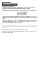
SECTION FIVE TECHNICAL SPECIFICATIONS Detection Range Up to 12 metres Detection Angle Power Supply 180º 240V ~ 50Hz Maximum Switchable Load 300W Lamp Type 118mm Linear Tungsten Halogen 300W max (R7S cap) Timer Control Adjustable 1 to 8 Hrs Time On Adjustment 5 seconds - 5 minutes Lux Level Adjustment Day & night or night only operation Environmental Protection IP44 (suitable for outdoor use) Halogen Lamp Replacement CAUTION Always handle quartz halogen bulbs with a soft cloth.
SECTION SIX TROUBLESHOOTING GUIDE PROBLEM SOLUTION o Lamp stays ON all the time at night. The unit may be suffering from false activation. Cover the sensor lens completely with a thick cloth. This will prevent the sensor from "seeing" anything. If the unit now switches off after the set time duration and does not re-activate, this indicates that the problem was caused by false activation. The problem may be solved by slightly adjusting the direction/ angle of the sensor head (see previous section).