Sapphire 9200 Series Pulse Generator Operating Manual Quantum Composers, Inc. P.O. Box 4248 Bozeman, MT 59772 1.800.510.6530 www.QuantumComposers.com sales@QuantumComposers.com 9200 Manual Version 1.
Contents 1. INTRODUCTION ........................................................................................................................................................ 4 TECHNICAL SUPPORT .................................................................................................................................................................. 4 WARRANTY ...........................................................................................................................................
Continuous Mode ........................................................................................................................................................... 20 Single Shot Mode ............................................................................................................................................................ 21 System Burst Mode Function .....................................................................................................................................
1. Introduction This manual is a reference designed to familiarize you with the Quantum Composers 9200 series pulse generator and is arranged so that you can easily find the information you’re looking for. Generally, each topic has its own section and no section assumes that yo u’ve read anything else in the manual.
2. Safety Issues Normal use of test equipment presents a certain amount of danger due to electrical shock because it may be necessary for testing to be performed where voltage is exposed. An electrical shock causing 10 milliamps of current to pass through the heart will stop most human heartbeats. Voltage as low as 35 VDC or 35 V RMS AC should be considered dangerous and hazardous, as it can produce a lethal current under certain conditions.
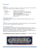
3. Front & Back Panel Overview Front Panel Indicators A total of up to 6 separate LED indicators are included on the front panel of the 9200. The following details the type of indication they represent. Quantum Logo Channel A-D Active Indicates the unit is powered on and system status. Indicates which channels are in the enabled state. Indicates the unit is armed and/or channels are actively pulsing (or waiting to be triggered).
Back Panel Indicators A total of up to 8 separate LED indicators are included on the back panel of the 9200.The following further details the type of indication they represent. PWR Channel A-D Active Gate/Trig Indicates the unit is powered on. Indicates which channels are in the enabled state. Indicates the armed channels are actively pulsing (or waiting to be triggered). Indicates which mode the external input is in. If neither is illuminated, the unit is in internally triggered mode.
4. Pulse Concepts and Pulse Generator Operations Counter Architecture Overview *Start source is: Run/Stop button/function in Internal Modes External input in External Trigger modes *TRG command via Serial access **Channels are armed by the Run/Stop function (external button or through 9200 application). In single shot and burst modes channels may be rearmed by pressing the RUN button again. System Timer Functions The System Timer functions as a non-retriggerable, multi-vibrator pulse generator.
Channel Timer Functions The Channel Timer functions as a non-retriggerable, delayed, one shot pulse generator. This means that the timer will only generate one delayed pulse for every start pulse received. Once the channel timer has started counting, additional start pulses will be ignored until the pulse has been completed (non-retriggerable). The start pulse for each channel is provided by the internal T 0 pulse generated by the internal system timer.
Navigating the 9200 Primary control of the 9200 is carried out either through the 9200 application (see 9200 application Menus) or through unit specific commands using a terminal program via USB (see Programming the 9200). Communication through Bluetooth is also available as an upgrade which will allow the same user interfaces as USB. The Run/Stop buttons found on either side of the 9200 serve the purpose of both power on/off as well as enablin g/disabling the system output.
5. 9200 Setup Overview The 9200 can easily be interfaced by means of the included 9200 application. On standard models, a USB cable and a port with USB 2.0 capabilities or greater (recommended) are required to communicate with the unit. Bluetooth is available as an option if wireless communication is required. If the equipment is used in a manner not specified by the manufacturer, the protection provided by the equipment may be impaired.
Driver Installation (Windows XP) 1. Plug the 9200 into the computer using a USB cable. Make sure the unit is powered on. 2. The computer will display a message indicating it has found new hardware: “QC-PG”. 3. The new hardware wizard will launch. Check the “Install from a list or specific location” option and click next. 4. Select “Search for the best driver in these locations” and check the option to “Include this location in the search”.
6. 9200 Application 9200 Application Overview Aside from using the SCPI command protocol, the included software application is the primary means of communication with the 9200. This application allows simple control of the 9200 unit via the USB or optional Bluetooth communications port. To run the software, simply double click on the application which can be found on the included CD. No installation is required. The software can also be copied to your computer and run from any location.
Basic Operation The following steps must be carried out before communication with the 9200 may take place: Ensure that the proper drivers have already been installed on the remote computer. These drivers will need to be installed for the remote computer to interface to the 9200. Reference the “9200 Setup USB” section for more information on installing the proper drivers. Open the 9200 application by double clicking on the application which can be found on the included CD.
Auto Start: Enables or disables the Auto Start function. If enabled, the unit will start pulsing immediately upon power-up or be in an armed state if in external mode. External Trigger/Gate: Selects the system’s External Mode to be Disabled, Triggered, or Gated. If either Triggered or Gated is selected, the following sub -parameters may be set. o Threshold (V): Sets the trigger threshold Voltage in 10mV increments.
Channel Mode: Changes the Channel Mode to Normal, Single Shot, Burst, or Duty Cycle. o Normal: Channel will produce pulses as long as a T 0 is present (mimics System Pulse Mode) o Duty Cycle: If Duty Cycle has been selected in the Channels section, the unit will generate a continuous pulse stream in which outputs will be On for “N” pulses and Off for “M” pulses.
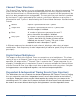
Parameter Storage Saving Custom Settings to a Bin The 9200 series has the capability to save up to 6 custom user setups. Once all the custom user settings are ready to be saved to one of six bins, click “Storage”, “Save To Bin”, followed by selecting the bin number to save the custom settings to. Figure 6.5 represents the saving process: Figure 6.5 –9200 Application: Recalling From Bin 9200 Manual Version 1.
Recalling Custom Settings from a Bin The 9200 series has the capability to recall any of the 6 custom user setups. If any of the previously saved presets are to be recalled, click “Storage”, “Restore From Bin”, followed by selecting the bin number to recall. Figure 6.6 represents the recalling process: *Note: Selecting Default 0 will set the 9200 to factory default settings. Figure 6.6 –9200 Application: Recalling From Bin Page 18 9200 Manual Version 1.
9200 Application Example This example will demonstrate the proper 9200 application settings for a specific scenario. The example will show how to output a single pulse on Channel-A upon receiving the rising edge of every external trigger signal at 5V. The output will have an amplitude of 4V, pulse width of 10us, and no channel delay present. Figure 6.7 –9200 application: Example 9200 Manual Version 1.
7. Operating the 9200 Normal Internal Rate Generator Operation The 9200 has a complete set of functions providing a number of modes of operation for the internal or “System” rate generator (T 0). Most of these functions can be ignored if a simple continuous stream of pluses is required.
Single Shot Mode Pressing the unit’s Run/Stop button generates a single pulse with every press. Set the following parameters in the 9200 application: Within the System section: o Select Single Shot mode. Within the Channel section: o Set channel mode to Normal. o Enter the required pulse width and delay. Repeat for each output channel. o Enable the corresponding channels by clicking “Enabled” in the 9200 application.
Within the System section: o Set the mode to Duty Cycle. o Set the On parameter to the number of pulses to produce during the on cycle (‘N’). o Set the Off parameter to the number of pulses to suppress during the off cycle (‘M’). o Set the desired Period. Within the Channel section: o Set channel mode to Normal. o Set the Sync Source to T 0 in each respective channel tab . o Enter the required pulse width and delay. Repeat for each output channel.
Channel Single Shot Function The Single Shot mode generates a single pulse every time the unit is placed into active mode. To use the channels’ single shot mode set the following parameters in the 9200 application: Within the System section: o Set the mode to Continuous. o Set the desired Period (regulates rate of single shots) Within the Channel section: o Set the mode to Single Shot. o Enter the required pulse width and delay. Repeat for each output channel.
Within the Channel section: o Set the On parameter to the number of pulses to produce during the on cycle (‘N’). o Set the Off parameter to the number of pulses to suppress during the off cycle (‘M’). o Enter the required pulse width and delay. Repeat for each output channel. o Enable the corresponding channels by clicking “Enabled” in the 9200 application. Pressing the unit’s Run/Stop button will place the unit into active mode and generate a pulse train based on the duty cycle settings.
Within the Channel section: o Set the mode to Normal. o Enter the required pulse width and delay. Repeat for each output channel. o Enable the corresponding channels by clicking “Enabled” in the 9200 application. Pressing the unit’s Run/Stop button will arm the unit. Once the unit is armed, it will generate a T0 pulse for every external trigger received. Pressing the unit’s Run/Stop button or clicking the 9200 application’s Run/Stop again will disarm the unit.
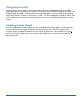
* System gated mode (Pulse Inhibit mode) prevents the channel from being triggered by the channels’ trigger source. When in Pulse Inhibit mode, if a pulse has already started when the gate is active, the channel pulse will continue normal output; although, the output will not restart on the next trigger pulse until the gate signal is asserted again. See “Output Examples” for a visual representation.
Output Examples The following figure presents a graphical representation of the channel modes as well as the external trigger/gate functionality. It should be noted that following figure represents examples only as many parameters in each pulse train below have the potential to be modified. 9200 Manual Version 1.
8. Programming the 9200 Personal Computer to 9200 Communication The 9200 uses USB as the standard interface. Bluetooth is also available as an additional interface. All settings can be set and retrieved over either interface using a simple command language or with the included 9200 application. The command set is structured to be consistent with the Standard Commands for Programmable Instruments (SCPI).
Line Termination The pulse generator uses text-style line terminations. When a command is sent to the unit, the firmware is programmed to read characters from a communication port until it reads the line termination sequence. The command string is parsed and executed after reading these characters. These characters are the “carriage return” and “linefeed”. They are ASCII character set values 13 and 10 respectively (hex 0x0D and 0x0A). All command strings need to have these characters appended.
SCPI Command Format SCPI commands control and set instrument specific functions such as setting the pulse width, delay, and period. SCPI commands have a hierarchical structure composed of functional elements that include a header or keywords separated with a colon, data parameters, and terminators. For example: SCPI Format :PULSE1:STATE ON :PULSe1:WIDTh 0.000120 :PULSe:POL NORMal Any parameter may be queried by sending the command with a question mark appended.
SCPI Parameter Types The following parameter types are used: Accepts all commonly used decimal representation of numbers including optional signs, decimal points, and scientific notation: For Example: 123, 123e2, -123, -1.23e2, .123, 1.23e2, 1.2300E-01 Represents a single binary condition that is either true or false. True is represented by a 1 or ON; false is represented by a 0 or OFF. Queries return 1 or 0. Selects from a finite number of predefined strings.
To start the pulses use either of the following commands: :PULSE0:STATE ON :INST:STATE ON starts the pulses alternate form to start pulses Example 2) 25μs pulse width, 0 delay, external trigger, and one pulse for every trigger. :PULSE1:STATE ON :PULSE1:POL NORM :PULSE:WIDT 0.000025 :PULSE1:DELAY 0 :PULSE0:MODE SING :PULSE:EXT:MODE TRIG :PULS:EXT:LEV 2.
9200 SCPI Command Summary Command Keyword 1 Keyword 2 Keyword 3 Parameter Range :INSTrument :CATalog ? :FULL ? :COMMands ? 0–4 :NSELect Command :SELect T 0 / CH[A-D] :STATe 0/1 or OFF/ON Keyword 1 Keyword 2 Keyword 3 :STATe 0/1 or OFF/ON :PERiod 200[ns] – 1000[s] :MODe NORMal/SINGle/ BURSt/DCYCle 9200 Manual Version 1.2 | Quantum Composers The units’ upper level command keyword. Returns a comma separated list of the names of all channels.
:PCOunter 1-1,000,000 :OCOunter 1-1,000,000 :EXTernal DISabled / TRIGger / GATe :MODe :LEVel 0.2 - 15[V] :EDGe RISing / FALLing :POLarity LOW / HIGH Changes the number of on pulses to output when the system is in Duty Cycle mode. *Note: The commas should be omitted. Changes the number of off pulses to suppress when the system is in Duty Cycle mode. *Note: The commas should be omitted.
:DELay +/-1000[s] :SYNC T0,CHA,CHB,CHC ,CHD :MUX 0-15 NORMal / COMPlement / INVerted :POLarity :OUTPut :AMPLitude :CMODe 3.3 - 5 [V] NORMal / SINGle / BURSt / DCYCle :BCOunter 1 to 1,000,000 :PCOunter 1 to 100,000 :OCOunter 1 to 100,000 :WCOunter 0 to 100,000 Sets the delay from the timing reference to when the pulse is created. The command should be sent without units. If for example 50ns is desired the parameter sent should be 50e-9, or the decimal equivalent.
:CGATe Command Keyword 1 DIS / LOW / HIGH Keyword 2 Keyword 3 Parameter Range :SYSTem :STATe ? :BEEPer :STATe 0/1 or OFF/ON :COMMunicate Channel Gate Subsystem. Contains commands to control using the gate input to control the output channel. Notes Command to change the units’ system settings. Query Only Command Command to change the units’ beeper settings. Command to turn on or off the systems' beeper. Command to set the communication settings.
IEEE 488.2 Common Commands Command: Parameter Range: *IDN ? *RCL *RST *SAV *SER *TRG 0-6 *ARM 1-6 ? Notes: Query only. Returns model, serial number, firmware version, and FPGA version numbers. Recalls configuration from specified storage location RESET. Resets parameters, same as *RCL 0 Saves current parameters to desired storage location Serial number query. Creates a soft trigger input. Resets all channel counters simultaneously when the channels are in either single shot or burst mode.
9. Appendix A – Specifications 9200 Specifications Indoor use in dry conditions only Ordinary Protection: This product is NOT protected against harmful ingress of moisture. Class III Equipment (external 5Vdc SELV power source) USB power draw from the USB Host Port: 5Vdc 0.5A Pollution Degree II (Micro-Ambient Pollution restricted to temporary conductivity caused by condensation). External Power Supply: Installation (Overvoltage) Category II for transient over-voltages.
Channel Timing Generator Pulse Width Range Width Accuracy Width Resolution Pulse Delay Range Delay Accuracy Delay Resolution Jitter (Channel to Channel) 10n 1,000 s 10ns + [0.0001 x (width + delay)] 10 ns -1,000 1,000 s 10ns + (0.
Output Module Output Impedance - Output Level Resolution - Output Current Rise Time (10% - 90%) Slew Rate Overshoot 2 50 Ohms 3.3 – 5.0 VDC into ≥ 1K ohm 1.7 – 2.5 VDC into 50 ohm 20 mV 5mA typical into 1K ohm 50mA typical into 50 ohm < 2ns typical @ 5V (High Imp) < 1ns typical @ 2.5V (50 ohm) V/ns < 100mV + 10% of pulse amplitude Communications Standard – USB 2.
10. Appendix B – Bluetooth Option Overview The Bluetooth wireless communications capability is an additional feature on the 9200 series. Upon proper installation of the Bluetooth device and drivers on the user end, the 9200 may be controlled in a wireless fashion by means of the same 9200 application or by using any generic communication terminal program. Power When using the Bluetooth option, the 9200 does not need to be directly connected to a USB 2.
A message will appear indicating when connect wirelessly to the 9200. When using any command terminal, be sure to set and/or confirm the baud rate is 115200 bps. One may now use the 9200 Application (see “9200 Application or any generic communication terminal program to begin wireless communications. o It should be noted that the 9200 Application automatically detects the port which the device is on.
11. Appendix C – Safety Symbols Safety Marking Symbols This section provides a description of the safety marking symbols that may appear on the instrument. These symbols provide information about potentially dangerous situations which can result in death, injury, or damage to the instrument and other components. Symbol Publication Description/Comment IEC 417, No. 5031 Direct current. IEC 417, No. 5032 Alternating current. IEC 417, No. 5033 Both direct and alternating current IEC 617-2 No.
require a Safety Ground (Protective Ground). ISO 3864, No. B.3.6 Background color yellow; symbol and outline - black Caution, risk of electric shock IEC 417, No. 5041 Background color yellow; symbol and outline - black Caution, hot surface ISO 3864, No. B.3.1 Background color yellow; symbol and outline - black IEC 417, No.
12. Appendix D – CE Declaration of Conformity . 9200 Manual Version 1.