User Guide Quantum MP High Performance DC Drive Size 1 and Size 2 45A to 700A, 480V two or four quadrant operation Part Number: 400526-01 Issue: A3 www.emersonct.
General Information The manufacturer accepts no liability for any consequences resulting from inappropriate, negligent or incorrect installation or adjustment of the optional operating parameters of the equipment or from mismatching the variable speed drive with the motor. The contents of this guide are believed to be correct at the time of printing.
1 Safety Information .................................5 5 1.1 1.2 1.3 1.4 1.5 1.6 1.7 1.8 1.9 1.10 Warnings, Cautions and Notes .............................5 Electrical safety - general warning ........................5 System design and safety of personnel ................5 Environmental limits ..............................................5 Access ..................................................................5 Fire protection .......................................................
11 Advanced Parameters .........................90 11.1 11.2 11.3 11.4 11.5 11.6 11.7 11.8 11.9 11.17 11.18 11.19 11.20 11.21 11.22 11.23 Menu 1: Speed reference ....................................96 Menu 2: Ramps .................................................100 Menu 3: Speed feedback and speed control .....103 Menu 4: Torque and current control ..................106 Menu 5: Motor and field control .........................108 Menu 6: Sequencer and clock ...........................
Safety Product Mechanical Electrical Information Information Installation Installation Getting Started Basic Running the SMARTCARD Optimization parameters Motor Operation 1 Safety Information 1.1 Warnings, Cautions and Notes 1.4 Environmental limits 1.5 Access Access must be restricted to authorized personnel only. Safety regulations which apply at the place of use must be complied with.
Safety Product Mechanical Electrical Information Information Installation Installation Getting Started Basic Running the SMARTCARD Optimization parameters Motor Operation 2 Product Information 2.
Safety Product Mechanical Electrical Information Information Installation Installation 2.2.1 Getting Started Basic Running the SMARTCARD Optimization parameters Motor Operation Onboard PLC Advanced Technical UL Diagnostics Parameters Data Information Typical short-term overload limits The maximum percentage overload limit changes depending on the selected motor Variations in motor rated current will result in changes in the maximum possible overload as detailed in the Advanced User Guide.
Safety Product Mechanical Electrical Information Information Installation Installation 2.4 Table 2-3 Getting Started Basic Running the SMARTCARD Optimization parameters Motor Operation Advanced Technical UL Diagnostics Parameters Data Information Compatible encoders Encoders compatible with Quantum MP Pr 3.38 (Fb07, 0.
Safety Product Mechanical Electrical Information Information Installation Installation 2.
Safety Product Mechanical Electrical Information Information Installation Installation Figure 2-6 Getting Started Basic Running the SMARTCARD Optimization parameters Motor Operation Onboard PLC Advanced Technical UL Diagnostics Parameters Data Information Quantum MP size 2 features and options AC Terminals Line Fuses L2 L1 L3 GND DANGER HIGH VOLTAGE SM-Keypad-LCD / SM-Keypad-LED Keypad connection SmartCard * Solutions Modules Field Fuses Machine Feedback Terminals Feedback, Automation or Fiel
Safety Product Mechanical Electrical Information Information Installation Installation 2.6.1 Getting Started Basic Running the SMARTCARD Optimization parameters Motor Operation Onboard PLC Advanced Technical UL Diagnostics Parameters Data Information Options available for Quantum MP All Solutions Modules are color-coded in order to make identification easy. The following table shows the color-code key and gives further details on their function.
Safety Product Mechanical Electrical Information Information Installation Installation Getting Started Basic Running the SMARTCARD Optimization parameters Motor Operation Onboard PLC Advanced Technical UL Diagnostics Parameters Data Information Table 2-4 Solutions Module identification Type Solutions Module Color Name Further Details Applications Processor (with CTNet) Moss Green Automation (Applications) White SM-Applications Plus 2nd processor for running pre-defined and /or customer created
Safety Product Mechanical Electrical Information Information Installation Installation 2.
Safety Product Mechanical Electrical Information Information Installation Installation Getting Started Basic Running the SMARTCARD Optimization parameters Motor Operation Onboard PLC Advanced Technical UL Diagnostics Parameters Data Information 3 Mechanical Installation For further information, refer to section 3.5.2 Enclosure sizing on page 21. 3.1 Safety 3.2.4 Follow the instructions WARNING The mechanical and electrical installation instructions must be adhered to.
Safety Product Mechanical Electrical Information Information Installation Installation 3.3 Getting Started Basic Running the SMARTCARD Optimization parameters Motor Operation Onboard PLC Advanced Technical UL Diagnostics Parameters Data Information Terminal cover removal WARNING WARNING 3.3.1 Isolation device The AC supply must be disconnected from the drive using an approved isolation device before any cover is removed from the drive or before any servicing work is performed.
Safety Product Mechanical Electrical Information Information Installation Installation 3.3.3 Getting Started Basic Running the SMARTCARD Optimization parameters Motor Operation Onboard PLC Advanced Technical UL Diagnostics Parameters Data Information Installation and removal of a Solutions Module Please power down the drive before removing / installing the Solutions Module.
Safety Product Mechanical Electrical Information Information Installation Installation 3.3.4 Getting Started Basic Running the SMARTCARD Optimization parameters Motor Operation Onboard PLC Advanced Technical UL Diagnostics Parameters Data Information Installation and removal of a Keypad.
Safety Product Mechanical Electrical Information Information Installation Installation 3.4 Getting Started Basic Running the SMARTCARD Optimization parameters Motor Operation Onboard PLC Advanced Technical UL Diagnostics Parameters Data Information Mounting method The Quantum MP can only be surface mounted. WARNING WARNING If the drive has been used at high load levels for a period of time, the heatsink can reach temperatures in excess of 70°C (158°F).
Safety Product Mechanical Electrical Information Information Installation Installation Getting Started Basic Running the SMARTCARD Optimization parameters Motor Operation Figure 3-6 Surface mounting the size 2 drive Onboard PLC Figure 3-7 Installing the mounting feet bracket - Size 1 2 19.25 L2 L1 Advanced Technical UL Diagnostics Parameters Data Information L3 GND DANGER HIGH VOLTAGE 9.00 24.75 Mounting Holes 0.438 Diameter (8) places 33.
Safety Product Mechanical Electrical Information Information Installation Installation 3.5 Enclosure 3.5.1 Enclosure layout Getting Started Basic Running the SMARTCARD Optimization parameters Motor Operation Onboard PLC Advanced Technical UL Diagnostics Parameters Data Information Please observe the clearances in the diagram below taking into account any appropriate notes for other devices / auxiliary equipment when planning the installation.
Safety Product Mechanical Electrical Information Information Installation Installation Getting Started Basic Running the SMARTCARD Optimization parameters Motor Operation Onboard PLC Advanced Technical UL Diagnostics Parameters Data Information Figure 3-9 Enclosure layout size 2 AC supply, contactor, line chokes 325 mm* (13 in) L2 L1 L3 Ensure minimum clearances are maintained for the drive. Forced convection air-flow must not be restricted by any object of cabling.
Safety Product Mechanical Electrical Information Information Installation Installation Getting Started Basic Running the SMARTCARD Optimization parameters Motor Operation • • enclosure Maximum permissible temperature in oC inside the Tint Reducing the number of drives in the enclosure Removing other heat-generating equipment The dimensions of the enclosure are required only for accommodating the equipment. The equipment is cooled by the forced air flow.
Safety Product Mechanical Electrical Information Information Installation Installation Getting Started Basic Running the SMARTCARD Optimization parameters Motor Operation 3.8 Electrical terminals - Size 1 3.8.
Safety Product Mechanical Electrical Information Information Installation Installation Table 3-5 Getting Started Basic Running the SMARTCARD Optimization parameters Motor Operation Dynamic Braking Resistor (DB+ and DB-) terminals Model Connection type All Slotted lug Table 3-6 Torque setting Wire gauge Advanced Technical UL Diagnostics Parameters Data Information Suppression Resistor (SR+ and SR-) terminals Model Connection type Wire gauge Torque setting Nm lb ft 14-10 AWG 4 2.
Safety Product Mechanical Electrical Information Information Installation Installation Table 3-8 Getting Started Basic Running the SMARTCARD Optimization parameters Motor Operation Drive auxiliary and machine armature terminal data Table 3-9 Onboard PLC Advanced Technical UL Diagnostics Parameters Data Information Drive 120 Vac logic terminals Model Connection type Torque setting Model Connection type Torque setting All Terminal block 0.5 Nm 0.4 lb ft All Terminal block 0.79 Nm 0.
Safety Product Mechanical Electrical Information Information Installation Installation 4 Getting Started Basic Running the SMARTCARD Optimization parameters Motor Operation Onboard PLC Advanced Technical UL Diagnostics Parameters Data Information Electrical Installation Many cable management features have been incorporated into the product and accessories, this chapter shows how to optimize them.
Safety Product Mechanical Electrical Information Information Installation Installation Quantum MP User Guide Issue: A3 Getting Started Basic Running the SMARTCARD Optimization parameters Motor Operation Onboard PLC Advanced Technical UL Diagnostics Parameters Data Information 27 www.emersonct.
Safety Product Mechanical Electrical Information Information Installation Installation Getting Started Basic Running the SMARTCARD Optimization parameters Motor Operation 4.1 Electrical connections/ Power connections 4.1.1 AC and DC connections Onboard PLC Advanced Technical UL Diagnostics Parameters Data Information To understand the function of the different power connections, refer to Figure 4-1 and Figure 4-2 for size 1 drives and Figure 4-3 and Figure 4-4 for the size 2 drives.
Safety Product Mechanical Electrical Information Information Installation Installation 3 Getting Started Basic Running the SMARTCARD Optimization parameters Motor Operation Onboard PLC Advanced Technical UL Diagnostics Parameters Data Information CAUTION:Verify Control Transformer is configured per Table 1 before applying input voltage! 150 VDC Input Voltage 208/240/380/416/480 VAC 50/60 Hz Motor Field 4 Motor Armature F1 F2 F3 F4 Connection 300 VDC F4 Connection F3 F6 7 M F1 F2 External
Safety Product Mechanical Electrical Information Information Installation Installation Getting Started Basic Running the SMARTCARD Optimization parameters Motor Operation Onboard PLC Advanced Technical UL Diagnostics Parameters Data Information Figure 4-2 Control connections, Quantum MP size 1 MP10 User Interface Board C1 E-Stop C2 System Interlocks C5 C6 Run C4 Motor Thermal Two wire Run Pr 6.
Safety Product Mechanical Electrical Information Information Installation Installation Getting Started Basic Running the SMARTCARD Optimization parameters Motor Operation Onboard PLC Advanced Technical UL Diagnostics Parameters Data Information Differential Signal Single Ended Signal Mentor MP +10 (10mA) Non-Inverting Input Inverting Input 0V Analog Input 2 Analog Input 3 Analog Output 1 1 2 3 4 5 6 7 8 9 10 11 12 SM-IO-120V Solutions Module in Mentor MP Slot 3 Analog Output 2 7 Motor Thermis
Safety Product Mechanical Electrical Information Information Installation Installation Getting Started Basic Running the SMARTCARD Optimization parameters Motor Operation Onboard PLC Advanced Technical UL Diagnostics Parameters Data Information Figure 4-3 Power connections for Quantum MP size 2 drives Quantum MP Size 2 E1 E3 F3B 2 F3A B E3F H8 H7 H6 H5 H4 230V 208V 190V E1F 3 A H3 H2 H1 230V 208V 190V BR1 T1 X1 1 115V MC X2 NOTES: See Table 2 for values.
Safety Product Mechanical Electrical Information Information Installation Installation 3 Getting Started Basic Running the SMARTCARD Optimization parameters Motor Operation Onboard PLC Advanced Technical UL Diagnostics Parameters Data Information CAUTION: Verify Control Transformer is configured per Table 1 before applying input voltage! 4 Motor Field Motor Armature F6 External Suppression Resistor Dynamic Brake Resistor F8 1 7 M 300 VDC Connection F4 A1 [A2] A2 [A1] 150 VDC Connection I
Safety Product Mechanical Electrical Information Information Installation Installation Getting Started Basic Running the SMARTCARD Optimization parameters Motor Operation Onboard PLC Advanced Technical UL Diagnostics Parameters Data Information Figure 4-4 Control connections for Quantum MP size 2 Drives From T1 Control Connections X1 X2 TB1 C1 E-Stop C2 System Interlocks C5 C6 Run C3 C4 Motor Thermal C5 Stop C6 C7 C8 Two wire Run Pr 6.40 = 0 C7 Run Three wire Stop/Run Pr 6.
Safety Product Mechanical Electrical Information Information Installation Installation Getting Started Basic Running the SMARTCARD Optimization parameters Motor Operation Onboard PLC Advanced Technical UL Diagnostics Parameters Data Information Single Ended Signal +10 (10mA) Mentor MP Non-Inverting Input Inverting Input 0V Analog Input 2 Analog Input 3 Analog Output 1 1 2 3 4 5 6 7 8 9 10 11 12 SM-IO-120V Solutions Module in Mentor MP Slot 3 Analog Output 2 7 Analog Speed Reference 2 8 Motor
Safety Product Mechanical Electrical Information Information Installation Installation 4.2 Getting Started Basic Running the SMARTCARD Optimization parameters Motor Operation Ground connections Figure 4-6 Onboard PLC Advanced Technical UL Diagnostics Parameters Data Information Location of ground connection, Size 2 The drive must be connected to the system ground of the AC supply. The ground wiring must conform to local regulations and codes of practice.
Safety Product Mechanical Electrical Information Information Installation Installation Getting Started Basic Running the SMARTCARD Optimization parameters Motor Operation Figure 4-7 Removing the MOV ground connection, Size 1 Onboard PLC Advanced Technical UL Diagnostics Parameters Data Information necessary where a dedicated transformer is used to supply the drive.
Safety Product Mechanical Electrical Information Information Installation Installation Table 4-5 Basic Running the SMARTCARD Optimization parameters Motor Operation Current ratings Model Table 4-6 Maximum continuous field current rating A QMP45A4(R) QMP75A4(R) QMP155A4(R) QMP210A4(R) 8 QMP350A4(R) QMP400A4(R) QMP550A4(R) QMP700A4(R) 20 4.5.
Safety Product Mechanical Electrical Information Information Installation Installation 4.8.
Safety Product Mechanical Electrical Information Information Installation Installation 4.9.1 Getting Started Basic Running the SMARTCARD Optimization parameters Motor Operation Onboard PLC Advanced Technical UL Diagnostics Parameters Data Information Ferraz Shawmut fuses Ferraz Shawmut fuses are recommended for the Quantum MP, Size 1.
Safety Product Mechanical Electrical Information Information Installation Installation Table 4-13 Getting Started Basic Running the SMARTCARD Optimization parameters Motor Operation Onboard PLC Advanced Technical UL Diagnostics Parameters Data Information Ferraz Shawmut semiconductor (line) fusing for 480V size 2 drives (Included in Quantum MP) Control Techniques number Model Fuse type Rating V Rating A Catalog number Auxiliary 10x38mm ferrule 690V 25A FR10GB69V25 3533-2569 A50QS450-4 370
Safety Product Mechanical Electrical Information Information Installation Installation 4.9.2 Getting Started Basic Running the SMARTCARD Optimization parameters Motor Operation Onboard PLC Advanced Technical UL Diagnostics Parameters Data Information Alternative fusing Please refer to section 12.2.1 Fuses on page 150.
Safety Product Mechanical Electrical Information Information Installation Installation Figure 4-11 Size 2 Getting Started Basic Running the SMARTCARD Optimization parameters Motor Operation Location of external suppressor resistor terminals, Figure 4-12 Onboard PLC Advanced Technical UL Diagnostics Parameters Data Information Protection circuit for an external suppression resistor To external suppression resistor 4.
Safety Product Mechanical Electrical Information Information Installation Installation Getting Started Basic Running the SMARTCARD Optimization parameters Motor Operation emission is not sufficient to cause interference to other equipment. When radio frequency emission must be limited the method used should be chosen to suit the situation. 4.12.
Safety Product Mechanical Electrical Information Information Installation Installation 4.12.5 Getting Started Basic Running the SMARTCARD Optimization parameters Motor Operation Surge immunity of control circuits - long cables and connections outside a building Onboard PLC Advanced Technical UL Diagnostics Parameters Data Information 4-22 for the connection details for the RJ45 connector.
Safety Product Mechanical Electrical Information Information Installation Installation Getting Started Basic Running the SMARTCARD Optimization parameters Motor Operation If a drive is on the end of the network chain then pins 1 and 8 should be linked together. This will connect an internal 120Ω termination resistor between RXTX and RX\TX\.
Safety Product Mechanical Electrical Information Information Installation Installation Getting Started Basic Running the SMARTCARD Optimization parameters Motor Operation Source parameter: Indicates the parameter being output by the terminal Mode parameter: Analog - indicates the mode of operation of the terminal, i.e. voltage 0-10V, current 4-20 mA etc. Onboard PLC Advanced Technical UL Diagnostics Parameters Data Information Digital - indicates the mode of operation of the terminal, i.e.
Safety Product Mechanical Electrical Information Information Installation Installation Figure 4-17 Getting Started Basic Running the SMARTCARD Optimization parameters Motor Operation Onboard PLC Advanced Technical UL Diagnostics Parameters Data Information Default terminal location and functions, Size 1 24 Vdc digital I/O, analog I/O, tach, encoder, and status relays Polarized signal connectors Encoder 120 Vac digital I/O C1 Status Status relay 2 relay 1 51 52 53 61 62 63 C16 11 Z Z\ + 0 31
Safety Product Mechanical Electrical Information Information Installation Installation Figure 4-19 Getting Started Basic Running the SMARTCARD Optimization parameters Motor Operation Onboard PLC Advanced Technical UL Diagnostics Parameters Data Information Default terminal wiring diagram, Size 1 and Size 2 C1 E-Stop 120 VAC C2 System Interlocks 0V 2 +24V input 3 0V 5 Non-inverting input 6 Inverting input Analog speed reference 1 C3 C4 1 SM-I/O 120V Digital Input 6 Single-ended signal
Safety Product Mechanical Electrical Information Information Installation Installation Getting Started Basic Running the SMARTCARD Optimization parameters Motor Operation 4.16 General 4.16.
Safety Product Mechanical Electrical Information Information Installation Installation Getting Started Basic Running the SMARTCARD Optimization parameters Motor Operation Precision reference analog input 1 5 6 8 Onboard PLC Advanced Technical UL Diagnostics Parameters Data Information Analog input 3 Non-inverting input Default function Thermistor Inverting input Type of input Unipolar voltage, unipolar current and thermistor Pr 7.15 (in01, 0.
Safety Product Mechanical Electrical Information Information Installation Installation 21 Getting Started Basic Running the SMARTCARD Optimization parameters Motor Operation 0V common 30 Onboard PLC Advanced Technical UL Diagnostics Parameters Data Information 0V common Common connection for all external devices Function Function Supply for external digital devices Function Drive enable Nominal output current 200 mA (including all digital I/O) Type Positive or negative logic digital input
Safety Product Mechanical Electrical Information Information Installation Installation 51 Relay 1 common 52 Relay 1 normally closed 53 Relay 1 normally open Getting Started Basic Running the SMARTCARD Optimization parameters Motor Operation Default function Drive OK indicator Contact voltage rating 240 Vac, installation over-voltage category II Contact maximum current rating 5 A AC 240 V 5 A DC 30 V resistive load 0.
Safety Product Mechanical Electrical Information Information Installation Installation 4.
Safety Product Mechanical Electrical Information Information Installation Installation 5 Getting Started Basic Running the SMARTCARD Optimization parameters Motor Operation Onboard PLC Advanced Technical UL Diagnostics Parameters Data Information Getting Started This chapter introduces the user interfaces, menu structure and security level of the drive. 5.1 Understanding the display There are two types of keypad available for the Quantum MP.
Safety Product Mechanical Electrical Information Information Installation Installation Getting Started Basic Running the SMARTCARD Optimization parameters Motor Operation Onboard PLC Advanced Technical UL Diagnostics Parameters Data Information Figure 5-3 Display modes Status Mode (Display not flashing) To enter Parameter Mode, press key or Timeout** Timeout** To return to Status Mode, press key Parameter Mode (Upper display flashing) When returning to Parameter Mode use the * Use Temporary Parame
Safety Product Mechanical Electrical Information Information Installation Installation 5.3 Getting Started Basic Running the SMARTCARD Optimization parameters Motor Operation Menu 0 (sub block) Onboard PLC Advanced Technical UL Diagnostics Parameters Data Information Coding The coding defines the attributes of the parameter as follows. Menu 0 can be accessed by 2 methods: 1. Pr 11.44 (SE14, 0.35) = 0. Sub block mode. 2. Pr 11.44 (SE14, 0.35) <>0. Linear mode. Coding Attribute {X.
Safety Product Mechanical Electrical Information Information Installation Installation 23.02 Getting Started NC PT 0 to 127 BU 0 The OR of Pr 23.03 to Pr 23.09. To be used by the SM-Keypad Plus. Parameter Value 23.03 1 23.04 2 23.05 4 23.06 8 23.07 16 23.08 32 23.09 64 23.03 - 23.09 Pre-defined sub block enable RW Bit US 0 to1 BU 1 Description Display 23.03 Set up 23.04 Diagnostic diAGnoS 23.05 Trips triPS 23.06 Speed loop SP LOOP 23.
Safety Product Mechanical Electrical Information Information Installation Installation Getting Started Basic Running the SMARTCARD Optimization parameters Motor Operation 5.6 Speed feedback Menu 0 Parameter Description Display 0.71 3.26 Fb01 0.72 3.51 0.73 0.74 3.53 3.52 0.75 3.34 0.76 0.77 0.78 0.79 0.80 3.36 3.38 3.39 3.27 0.
Safety Product Mechanical Electrical Information Information Installation Installation 5.7 Getting Started Basic Running the SMARTCARD Optimization parameters Motor Operation Advanced menus Table 5-3 The advanced menus consist of groups or parameters appropriate to a specific function or feature of the drive. Menus 0 to 23 can be viewed on both keypads. Menus 40 and 41 are specific to the SM-Keypad Plus (LCD).
Safety Product Mechanical Electrical Information Information Installation Installation 5.9 Getting Started Basic Running the SMARTCARD Optimization parameters Motor Operation Restoring parameter defaults 5.10 Restoring parameter defaults by this method saves the default values in the drive’s memory. (Pr 11.44 (SE14, 0.35) and Pr 11.30 are not affected by this procedure).
Safety Product Mechanical Electrical Information Information Installation Installation 5.12.1 Getting Started Basic Running the SMARTCARD Optimization parameters Motor Operation Onboard PLC Advanced Technical UL Diagnostics Parameters Data Information User security The user security, when set, prevents write access to any of the parameters (other than Pr 11.44 (SE14, 0.35) Access Level) in any menu. Figure 5-8 User security open User security open - All parameters: Read / Write access Pr 0.00 Pr 0.
Safety Product Mechanical Electrical Information Information Installation Installation Getting Started 5.13 Serial communications 5.13.1 Introduction Basic Running the SMARTCARD Optimization parameters Motor Operation • Modbus RTU • CT ANSI Modbus RTU has been set as the default protocol, as it is used with the PC-tools commissioning/start-up software as provided on the CD ROM. Si01 Baud rate {0.66/11.
Safety Product Mechanical Electrical Information Information Installation Installation 6 Getting Started Basic Running the SMARTCARD Optimization parameters Motor Operation Onboard PLC Advanced Technical UL Diagnostics Parameters Data Information Basic parameters The pre-defined sub blocks contain commonly used parameters for basic set-up of the Quantum MP. All parameters in the pre-defined sub blocks appear in other menus in the drive. (Denoted by {x.xx} in Table 6-1.
Safety Product Mechanical Electrical Information Information Installation Installation Getting Started Basic Running the SMARTCARD Optimization parameters Motor Operation Range() Parameter Fb09 Drive encoder speed feedback {0.79, 3.27} in01 Analog input 3 mode {0.81, 7.
Safety Product Mechanical Electrical Information Information Installation Installation 6.1.2 Getting Started Basic Running the SMARTCARD Optimization parameters Motor Operation Set-up Bi all bits equal to zero gives 1, PT ±SPEED_LIMIT_MAX rpm Pr 1.41 = 1 then Pr 1.49 = 2 Pr 1.42 = 1 then Pr 1.49 = 3 Pr 1.43 = 1 then Pr 1.49 = 4 Pr 1.44 = 1 then Pr 1.49 = 5 Pr 1.52 = 1 then Pr 1.49 = 6 US 0.0 (When the drive is jogging, this parameter has no effect.) Set SE01 (Pr 0.22, 1.
Safety Product Mechanical Electrical Information Information Installation Installation Getting Started Basic Running the SMARTCARD Optimization parameters Motor Operation Advanced Technical UL Diagnostics Parameters Data Information removed either from the enable input, or Pr 6.15 is set to zero or from the control word (Pr 6.42) if it is active. SE09 Parameter copying {0.30, 11.
Safety Product Mechanical Electrical Information Information Installation Installation Getting Started Basic Running the SMARTCARD Optimization parameters Motor Operation Onboard PLC Advanced Technical UL Diagnostics Parameters Data Information Figure 6-1 di02 Pre-ramp reference {0.37, 1.03} RO Bi NC ±MAX_SPEED_REF rpm PT Bi NC ±SPEED_MAX rpm Bi PT FI ±SPEED_MAX rpm Figure 6-1 shows the filter arrangement.
Safety Product Mechanical Electrical Information Information Installation Installation di08 {0.43, 4.01} RO Uni Getting Started Basic Running the SMARTCARD Optimization parameters Motor Operation 6.1.4 Current magnitude FI 0 to DRIVE_CURRENT_MAX A NC RO Bi NC PT RO Bi tr07 Trip 6 {0.57, 10.26} tr08 Trip 7 {0.58, 10.27} Armature voltage FI ±ARMATURE_VOLTAGE_ MAX V tr04 Trip 3 {0.54, 10.23} tr06 Trip 5 {0.56, 10.25} Indicates the field current feedback in 0.01 amperes. di10 {0.
Safety Product Mechanical Electrical Information Information Installation Installation Getting Started Basic Running the SMARTCARD Optimization parameters Motor Operation SP03 (Kd1) Speed controller differential feedback gains {0.63, 3.12} RW Uni US 0.00000 to 0.65535 (1/s / (rad/s)) 0.00000 Onboard PLC Advanced Technical UL Diagnostics Parameters Data Information feedback category Solutions Module is not installed in slot 1 the drive produces an EnC9 trip.
Safety Product Mechanical Electrical Information Information Installation Installation Getting Started Basic Running the SMARTCARD Optimization parameters Motor Operation The encoder supply voltage present on the drive encoder connector is defined by this parameter as 0 (5V), 1 (8V), 2 (15V) or 3 (24V) Onboard PLC Advanced Technical UL Diagnostics Parameters Data Information Parameter value Parameter string Mode 0 0-20 0 - 20 mA 1 20-0 20 - 0 mA 2 4-20.
Safety Product Mechanical Electrical Information Information Installation Installation 7 Getting Started Basic parameters Running the Motor Optimization SMARTCARD Operation Onboard PLC Advanced Technical UL Diagnostics Parameters Data Information Running the Motor This chapter takes the new user through all the essential steps to running a motor for the first time, in each of the possible operating modes. Verify 120 Vac control transformer is configured per Table 46.
Safety Product Mechanical Electrical Information Information Installation Installation 7.
Safety Product Mechanical Electrical Information Information Installation Installation Getting Started Basic parameters Action Running the Motor Optimization SMARTCARD Operation Onboard PLC Advanced Technical UL Diagnostics Parameters Data Information Detail Quantum MP is able to perform either a static, rotating or continuous autotune. The motor must be at a standstill before an autotune is enabled.
Safety Product Mechanical Electrical Information Information Installation Installation 7.
Safety Product Mechanical Electrical Information Information Installation Installation Getting Started Basic parameters Running the Motor Optimization Action SMARTCARD Operation Onboard PLC Advanced Technical UL Diagnostics Parameters Data Information Detail Quantum MP is able to perform either a static, rotating or continuous autotune. The motor must be at a standstill before an autotune is enabled.
Safety Product Mechanical Electrical Information Information Installation Installation 7.3 Getting Started Basic parameters Running the Motor CTSoft software commissioning tool CTSoft can be used for commissioning and monitoring, drive parameters can be uploaded, downloaded and compared, and simple or custom menu listings can be created. Drive menus can be displayed in standard list format or as live block diagrams.
Safety Product Mechanical Electrical Information Information Installation Installation 8 Getting Started Basic Running the SMARTCARD Onboard Optimization parameters Motor Operation PLC Optimization speed feedback device) The Rotating Autotune (Pr 5.12 (SE13, 0.34) = 2) sets up the field controller for more accurate flux control and open loop speed accuracy.
Safety Product Mechanical Electrical Information Information Installation Installation 8.4.2 Getting Started Basic Running the SMARTCARD Optimization parameters Motor Operation Continuous autotune for current loop gains In the static autotune the armature current loop gains are set up with no flux in the motor. In some motors the inductance of the armature charges significantly when flux is present in the machine.
Safety Product Mechanical Electrical Information Information Installation Installation 8.6 Getting Started Basic Running the SMARTCARD Onboard Optimization parameters Motor Operation PLC Advanced Technical UL Diagnostics Parameters Data Information Current limit tapers With some motors the commutation limit of the motor requires that the maximum armature current be reduced at higher speeds, the current limit tapers can be used to provide this speed dependent current limit.
Safety Product Mechanical Electrical Information Information Installation Installation 9 Getting Started Basic Running the SMARTCARD Onboard Advanced Technical UL Diagnostics Optimization parameters Motor Operation PLC Parameters Data Information SMARTCARD Operation Either of these indications will tell the user that data is being transferred to or from the SMARTCARD: • NOTE Quantum MP default parameter values are stored on the SMARTCARD that was shipped with the drive. See section 5.
Safety Product Mechanical Electrical Information Information Installation Installation 9.3.1 Getting Started Basic Running the SMARTCARD Onboard Advanced Technical UL Diagnostics Optimization parameters Motor Operation PLC Parameters Data Information Writing to the SMARTCARD 3yyy - Transfer data to the SMARTCARD The data block contains the complete parameter data from the drive, i.e. all user-save (US) parameters except parameters with the NC coding bit set.
Safety Product Mechanical Electrical Information Information Installation Installation 9.3.6 Getting Started Basic Running the SMARTCARD Onboard Advanced Technical UL Diagnostics Optimization parameters Motor Operation PLC Parameters Data Information Comparing drive full parameter set with the SMARTCARD values Setting 8yyy in Pr xx.00, will compare the SMARTCARD file with the data in the drive: • • If the compare is successful Pr xx.00 is simply set to 0 If the compare fails a ‘C.
Safety Product Mechanical Electrical Information Information Installation Installation Getting Started Basic Running the SMARTCARD Onboard Advanced Technical UL Diagnostics Optimization parameters Motor Operation PLC Parameters Data Information This parameter gives the checksum of the data block, space left on the card, the total space on the card or the card flags. Refer to Pr 11.37 for information. 11.42 Parameter copying (SE09, 0.
Safety Product Mechanical Electrical Information Information Installation Installation 9.6 Getting Started Basic Running the SMARTCARD Onboard Advanced Technical UL Diagnostics Optimization parameters Motor Operation PLC Parameters Data Information SMARTCARD trips After an attempt to read, write or erase data to or from a SMARTCARD a trip may occur if there has been a problem with the command.
Safety Product Mechanical Electrical Information Information Installation Installation Table 9-7 Lower display Getting Started Basic Running the SMARTCARD Onboard Advanced Technical UL Diagnostics Optimization parameters Motor Operation PLC Parameters Data Information SMARTCARD status indications Description boot A parameter set is being transferred from the SMARTCARD to the drive during power-up. For further information please refer to section 9.3.
Safety Product Mechanical Electrical Information Information Installation Installation Getting Started Basic Running the SMARTCARD Onboard Advanced Technical UL Diagnostics Optimization parameters Motor Operation PLC Parameters Data Information 10 Onboard PLC 10.1 Onboard PLC and SYPT Lite • Advantages of SYPT Lite: There are no real-time tasks, i.e. the scheduling rate of the program cannot be guaranteed. SM-Applications Plus tasks such as Clock, Event, Pos0 or Speed are not available.
Safety Product Mechanical Electrical Information Information Installation Installation Basic Running the SMARTCARD Onboard Advanced Technical UL Diagnostics Optimization parameters Motor Operation PLC Parameters Data Information Programming options for Quantum MP FUNCTIONALITY Figure 10-2 Getting Started Level 4 SM-Applications Plus with SYPT software Level 3 SM-Applications Lite V2 with SYPT software Level 2 SM-Applications Lite V2 with SYPTLite software Level 1 Onboard PLC with SYPTLite software
Safety Product Mechanical Electrical Information Information Installation Installation Getting Started Basic Running the SMARTCARD Onboard Advanced Technical UL Diagnostics Optimization parameters Motor Operation PLC Parameters Data Information 10.6 11.48 RO Drive Onboard PLC program status Bi NC -128 to +127 Onboard PLC trips The following trips are associated with the Onboard PLC program.
Safety Product Mechanical Electrical Information Information Installation Installation 11 Getting Started Basic Running the SMARTCARD Onboard Advanced Technical UL Diagnostics Optimization parameters Motor Operation PLC Parameters Data Information Advanced Parameters Coding This is a quick reference to all parameters in the drive showing units, ranges, limits etc, with block diagrams to illustrate their function.
Safety Product Mechanical Electrical Information Information Installation Installation Getting Started Basic Running the SMARTCARD Onboard Advanced Technical UL Diagnostics Optimization parameters Motor Operation PLC Parameters Data Information Table 11-3 Feature look-up table Feature Acceleration rates Analog speed reference 1 Analog speed reference 2 Analog I/O Analog input 1 Analog input 2 Analog input 3 Analog output 1 Analog output 2 Application menu At speed indicator bit Auto reset Autotune Binary
Safety Product Mechanical Electrical Information Information Installation Installation Feature Motor map Motor map 2 Motorized potentiometer Offset speed reference Onboard PLC Open collector digital outputs Orientation Output Overspeed threshold PID controller Position feedback - drive Positive logic Power up parameter Precision reference Preset speeds Programmable logic Regenerating Relative jog Relay output Reset S ramp Security code Serial comms Skip speeds SMARTCARD Software version Speed controller Sp
Safety Product Mechanical Electrical Information Information Installation Installation Getting Started Basic Running the SMARTCARD Onboard Advanced Technical UL Diagnostics Optimization parameters Motor Operation PLC Parameters Data Information Parameter ranges and variable maximums: The two values provided define the minimum and maximum values for the given parameter.
Safety Product Mechanical Electrical Information Information Installation Installation Getting Started Basic Running the SMARTCARD Onboard Advanced Technical UL Diagnostics Optimization parameters Motor Operation PLC Parameters Data Information Maximum ARMATURE_VOLTAGE_MAX [1025] Definition Maximum armature voltage Vac x 1.35 (√2 x 3 / π) 480 +10% drive: 720 575 +10% drive: 860 690 +10% drive: 1025 NOTE For 4 quadrant drives maximum armature voltage = Vac x 1.
Safety Product Mechanical Electrical Information Information Installation Installation Quantum MP User Guide Issue: A3 Getting Started Basic Running the SMARTCARD Onboard Advanced Technical UL Diagnostics Optimization parameters Motor Operation PLC Parameters Data Information 95 www.emersonct.
Safety Product Mechanical Electrical Information Information Installation Installation 11.1 Getting Started Basic Running the SMARTCARD Onboard Advanced Technical UL Diagnostics Optimization parameters Motor Operation PLC Parameters Data Information Menu 1: Speed reference Menu 1 controls the main reference selection. Figure 11-1 Menu 1 logic diagram LOCAL/REMOTE Analog reference Analog input 1 Analog reference 1 Menu 8 1.36 Menu 7 1.41 Analog reference 2 select 1.42 Preset reference select 1.
Safety Product Mechanical Electrical Information Information Installation Installation Getting Started Basic Running the SMARTCARD Onboard Advanced Technical UL Diagnostics Optimization parameters Motor Operation PLC Parameters Data Information JOG RUN FORWARD FORWARD / REVERSE C10 C8 C12 Menu 17 Menu 6 Sequencer Sequencer (Menu 6) Jog selected indicator Bipolar reference select Reference in skip speed band indicator 1.13 Menu 13 Position control 1.10 1.
Safety Product Mechanical Electrical Information Information Installation Installation Getting Started Basic Running the SMARTCARD Onboard Advanced Technical UL Diagnostics Optimization parameters Motor Operation PLC Parameters Data Information Range() Parameter 1.01 1.02 1.03 1.04 1.05 1.06 1.07 1.08 1.09 1.10 1.11 1.12 1.13 1.14 1.15 1.16 1.17 1.18 1.19 1.20 1.21 1.22 1.23 1.24 1.25 1.26 1.27 1.28 1.29 1.30 1.31 1.32 1.33 1.34 1.35 1.36 1.37 1.38 1.39 1.40 1.41 1.42 1.43 1.44 1.45 1.46 1.47 1.48 1.
Safety Product Mechanical Electrical Information Information Installation Installation Quantum MP User Guide Issue: A3 Getting Started Basic Running the SMARTCARD Onboard Advanced Technical UL Diagnostics Optimization parameters Motor Operation PLC Parameters Data Information 99 www.emersonct.
Safety Product Mechanical Electrical Information Information Installation Installation 11.2 Getting Started Basic Running the SMARTCARD Onboard Advanced Technical UL Diagnostics Optimization parameters Motor Operation PLC Parameters Data Information Menu 2: Ramps The pre-ramp speed reference passes through the ramp block controlled by menu 2 before being used by the drive to produce input to the speed controller.
Safety Product Mechanical Electrical Information Information Installation Installation Quantum MP User Guide Issue: A3 Getting Started Basic Running the SMARTCARD Onboard Advanced Technical UL Diagnostics Optimization parameters Motor Operation PLC Parameters Data Information 101 www.emersonct.
Safety Product Mechanical Electrical Information Information Installation Installation Getting Started Basic Running the SMARTCARD Onboard Advanced Technical UL Diagnostics Optimization parameters Motor Operation PLC Parameters Data Information Range() Parameter Post ramp reference Ramp enable Ramp hold Ramp output selector S ramp enable 2.07 0 to 100.000 s2/1000rpm Acceleration rate selector 0 to 9 Acceleration rate 1 {SE03, 0.24} 0 to MAX_RAMP_RATE s / (Pr 1.06 OR Pr 2.
Safety Product Mechanical Electrical Information Information Installation Installation 11.3 Getting Started Basic Running the SMARTCARD Onboard Advanced Technical UL Diagnostics Optimization parameters Motor Operation PLC Parameters Data Information Menu 3: Speed feedback and speed control Speed accuracy and resolution Digital reference resolution When a preset speed is used the reference resolution is 0.1rpm. Improved resolution can be obtained by using the precision reference (0.001rpm).
Safety Product Mechanical Electrical Information Information Installation Installation Getting Started Basic Running the SMARTCARD Onboard Advanced Technical UL Diagnostics Optimization parameters Motor Operation PLC Parameters Data Information Figure 11-3 Menu 3 logic diagram 104 www.emersonct.
Safety Product Mechanical Electrical Information Information Installation Installation Getting Started Basic Running the SMARTCARD Onboard Advanced Technical UL Diagnostics Optimization parameters Motor Operation PLC Parameters Data Information Range() Parameter 3.01 3.02 3.03 3.04 3.05 3.06 3.07 3.08 3.09 3.10 3.11 3.12 3.13 3.14 3.15 3.16 3.17 Final speed reference {di04, 0.39} Speed feedback {di05, 0.40} Speed error Speed controller output {di06, 0.
Safety Product Mechanical Electrical Information Information Installation Installation 11.4 Getting Started Basic Running the SMARTCARD Onboard Advanced Technical UL Diagnostics Optimization parameters Motor Operation PLC Parameters Data Information Menu 4: Torque and current control MOTOR1_CURRENT_LIMIT_MAX is used as the maximum for some parameters such as the user current limits.
Safety Product Mechanical Electrical Information Information Installation Installation Getting Started Basic Running the SMARTCARD Onboard Advanced Technical UL Diagnostics Optimization parameters Motor Operation PLC Parameters Data Information Range() Parameter 4.01 4.02 4.03 4.04 4.05 4.06 4.07 4.08 4.09 4.10 4.11 4.12 4.13 4.14 4.15 4.16 4.18 4.19 4.20 4.22 4.23 4.24 4.27 4.28 4.29 4.30 4.31 4.32 Current magnitude {di08, 0.43} Filtered current magnitude Torque demand {di07, 0.
Safety Product Mechanical Electrical Information Information Installation Installation 11.5 Getting Started Basic Running the SMARTCARD Onboard Advanced Technical UL Diagnostics Optimization parameters Motor Operation PLC Parameters Data Information Menu 5: Motor and field control Figure 11-5 Menu 5 field control logic diagram Maximum flux / Voltage limit Voltage error to % error conversion 1 Back emf set-point + 5.59 Base speed Field weakening voltage loop P gain 5.08 5.62 3.02 5.
Safety Product Mechanical Electrical Information Information Installation Installation Getting Started Basic Running the SMARTCARD Onboard Advanced Technical UL Diagnostics Optimization parameters Motor Operation PLC Parameters Data Information Enable field economy timeout 5.65 Drive active Field economy active Field economy level Sequencer run & 5.79 10.02 Power-up OR 5.80 Field economy level select 5.67 Field controller supply 5.76 Drive reset 5.
Safety Product Mechanical Electrical Information Information Installation Installation Getting Started Basic Running the SMARTCARD Onboard Advanced Technical UL Diagnostics Optimization parameters Motor Operation PLC Parameters Data Information Figure 11-6 Menu 5 armature control logic diagram Armature voltage 5.02 Output power Armature current Power calculation 4.02 5.10 Read-write (RW) parameter Output terminals 0.XX Read-only (RO) parameter 5.11 5.
Safety Product Mechanical Electrical Information Information Installation Installation Getting Started Basic Running the SMARTCARD Onboard Advanced Technical UL Diagnostics Optimization parameters Motor Operation PLC Parameters Data Information Range() Parameter 5.01 5.02 5.03 5.04 5.05 5.06 5.07 5.08 Armature firing angle Armature voltage Output power Estimated speed Line voltage Machine armature voltage Motor rated current Base speed {SE07, 0.28} {SE08, 0.29} 0 to 175.
Safety Product Mechanical Electrical Information Information Installation Installation 11.6 Getting Started Basic Running the SMARTCARD Onboard Advanced Technical UL Diagnostics Optimization parameters Motor Operation PLC Parameters Data Information Menu 6: Sequencer and clock Figure 11-7 Menu 6 logic diagram Control word enable Stop / Start select 6.43 Control word 6.42 6.04 Sequencer Drive enable 6.15 Run forward 6.30 C14 digital input 5 Jog forward 6.31 C14 Run reverse 6.
Safety Product Mechanical Electrical Information Information Installation Installation Getting Started Basic Running the SMARTCARD Onboard Advanced Technical UL Diagnostics Optimization parameters Motor Operation PLC Parameters Data Information Range() Default() 0 to 2 OFF (0) or On (1) 0 to 4 OFF (0) or On (1) 0 to 1 OFF (0) or On (1) 0 to 2 OFF (0) or On (1) 0 to 600.0 currency units per kWh OFF (0) or On (1) 0 to 30,000 hrs OFF (0) or On (1) 0 to 9.364 Years.Days 0 to 23.59 Hours.Minutes 0 to 9.
Safety Product Mechanical Electrical Information Information Installation Installation 11.7 Getting Started Basic Running the SMARTCARD Onboard Advanced Technical UL Diagnostics Optimization parameters Motor Operation PLC Parameters Data Information Menu 7: Analog I/O Figure 11-8 Menu 7 logic diagram Analog input 1 Analog input 1 offset 7.01 7.30 Analog input 1 Analog input 1 destination parameter 7.10 Any unprotected variable parameter + + A/D ??.?? 7.08 Analog input 1 scaling 1.36 ??.
Safety Product Mechanical Electrical Information Information Installation Installation Getting Started Basic Running the SMARTCARD Onboard Advanced Technical UL Diagnostics Optimization parameters Motor Operation PLC Parameters Data Information Range() Parameter 7.01 7.02 7.03 7.04 7.08 7.09 7.10 7.11 7.12 7.13 7.14 7.15 7.16 7.17 7.18 7.19 7.20 7.21 7.22 7.23 7.24 7.28 7.29 7.30 7.31 7.32 7.34 RW FI T5/6 analog input 1 {in02, 0.82} T7 analog input 2 {in03, 0.83} T8 analog input 3 {in04, 0.
Safety Product Mechanical Electrical Information Information Installation Installation 11.8 Getting Started Basic Running the SMARTCARD Onboard Advanced Technical UL Diagnostics Optimization parameters Motor Operation PLC Parameters Data Information Menu 8: Digital I/O Figure 11-9 Menu 8 logic diagram T24 digital I/O 1 state 8.01 T24 output select ??.?? 10.03 8.31 ??.?? x(-1) T24 digital I/O 1 8.29 I/O polarity select T24 digital I/O 1 source/ destination 8.30 8.
Safety Product Mechanical Electrical Information Information Installation Installation Figure 11-10 Getting Started Basic Running the SMARTCARD Onboard Advanced Technical UL Diagnostics Optimization parameters Motor Operation PLC Parameters Data Information Menu 8 logic diagram (cont) T27 digital input 4 state 8.04 T27 digital input 4 invert Stop/start logic select T27 digital input 4 destination 8.14 6.04 8.24 Any unprotected bit parameter T27 digital input 4 ??.?? 8.29 I.
Safety Product Mechanical Electrical Information Information Installation Installation Getting Started Basic Running the SMARTCARD Onboard Advanced Technical UL Diagnostics Optimization parameters Motor Operation PLC Parameters Data Information Figure 11-11 Menu 8 logic diagram (cont) Relay source Relay source invert 8.27 Any bit parameter Relay state Relay 1 Drive Healthy x(-1) Relay source Relay source invert 8.
Safety Product Mechanical Electrical Information Information Installation Installation Getting Started Basic Running the SMARTCARD Onboard Advanced Technical UL Diagnostics Optimization parameters Motor Operation PLC Parameters Data Information Range() Parameter Default() Type 8.01 T24 digital I/O 1 state {in05, 0.85} OFF (0) or On (1) RO Bit NC PT 8.02 T25 digital I/O 2 state {in06, 0.86} OFF (0) or On (1) RO Bit NC PT 8.03 T26 digital I/O 3 state {in07, 0.
Safety Product Mechanical Electrical Information Information Installation Installation 11.9 Getting Started Basic Running the SMARTCARD Onboard Advanced Technical UL Diagnostics Optimization parameters Motor Operation PLC Parameters Data Information Menu 9: Programmable logic, motorized pot and binary sum The External Trip input (Terminal C4 = Input 6 on the SM-I/O120V Module) is conditioned using the programmable logic to prevent the drive from powering up in the External Trip state.
Safety Product Mechanical Electrical Information Information Installation Installation Figure 11-13 Getting Started Basic Running the SMARTCARD Onboard Advanced Technical UL Diagnostics Optimization parameters Motor Operation PLC Parameters Data Information Menu 9 logic diagram: Motorized pot and binary sum Motorized pot. bipolar select Motorized pot. rate Motorized pot. output indicator Motorized pot. destination parameter 9.22 9.23 9.03 9.25 Motorized pot.
Safety Product Mechanical Electrical Information Information Installation Installation Getting Started Basic Running the SMARTCARD Onboard Advanced Technical UL Diagnostics Optimization parameters Motor Operation PLC Parameters Data Information Range() Parameter 9.01 9.02 9.03 9.04 9.05 9.06 9.07 9.08 9.09 9.10 9.14 9.15 9.16 9.17 9.18 9.19 9.20 9.21 9.22 9.23 9.24 9.25 9.26 9.27 9.28 9.29 9.30 9.31 9.32 9.33 9.34 9.35 9.36 9.37 9.
Safety Product Mechanical Electrical Information Information Installation Installation 11.10 Basic Running the SMARTCARD Onboard Advanced Technical UL Diagnostics Optimization parameters Motor Operation PLC Parameters Data Information Menu 10: Status and trips Parameter 10.01 10.02 10.03 10.04 10.05 10.06 10.07 10.08 10.09 10.10 10.13 10.14 10.17 10.18 10.19 10.20 10.21 10.22 10.23 10.24 10.25 10.26 10.27 10.28 10.29 10.32 10.33 10.34 10.35 10.36 10.38 10.40 10.41 10.42 10.43 10.44 10.45 10.46 10.47 10.
Safety Product Mechanical Electrical Information Information Installation Installation 11.11 Getting Started Basic Running the SMARTCARD Onboard Advanced Technical UL Diagnostics Optimization parameters Motor Operation PLC Parameters Data Information Menu 11: General drive set-up Parameter 11.21 11.22 11.23 11.24 11.25 11.26 11.29 11.30 11.32 11.33 11.34 11.35 11.36 11.37 11.38 11.39 11.40 11.41 11.42 11.44 11.45 11.46 11.47 11.48 11.49 11.50 11.51 11.52 11.53 11.55 11.56 11.57 11.58 11.59 11.60 11.
Safety Product Mechanical Electrical Information Information Installation Installation 11.12 Figure 11-14 Getting Started Basic Running the SMARTCARD Onboard Advanced Technical UL Diagnostics Optimization parameters Motor Operation PLC Parameters Data Information Menu 12: Threshold detectors, variable selectors and brake control function Menu 12 logic diagram Threshold Detector 1 Threshold Detector 1 output indicator Threshold Detector 1 threshold level 12.
Safety Product Mechanical Electrical Information Information Installation Installation Getting Started Basic Running the SMARTCARD Onboard Advanced Technical UL Diagnostics Optimization parameters Motor Operation PLC Parameters Data Information Figure 11-15 Menu 12 logic diagram (continued) Variable Selector 1 Any variable parameter Variable selector 1 output indicator Variable selector 1 input 1 scaling ??.?? Variable selector 1 output destination 12.13 12.12 ??.
Safety Product Mechanical Electrical Information Information Installation Installation Figure 11-16 Getting Started Basic Running the SMARTCARD Onboard Advanced Technical UL Diagnostics Optimization parameters Motor Operation PLC Parameters Data Information Menu 12 Brake control function 12.51 Flux feedback External field control Enable position controller during brake release Drive active 2.03 Ramp hold 10.02 _ 80% x Rated field current Position control mode ( = 1) 12.49 + 5.54 13.10 12.
Safety Product Mechanical Electrical Information Information Installation Installation Getting Started Basic Running the SMARTCARD Onboard Advanced Technical UL Diagnostics Optimization parameters Motor Operation PLC Parameters Data Information Range() Parameter 12.01 12.02 12.03 12.04 12.05 12.06 12.07 12.08 12.09 12.10 12.11 12.12 12.13 12.14 12.15 12.23 12.24 12.25 12.26 12.27 12.28 12.29 12.30 12.31 12.32 12.33 12.34 12.35 12.40 12.41 12.43 12.45 12.46 12.47 12.48 12.49 12.50 12.
Safety Product Mechanical Electrical Information Information Installation Installation Quantum MP User Guide Issue: A3 Getting Started Basic Running the SMARTCARD Onboard Advanced Technical UL Diagnostics Optimization parameters Motor Operation PLC Parameters Data Information 129 www.emersonct.
Safety Product Mechanical Electrical Information Information Installation Installation 11.13 Getting Started Basic Running the SMARTCARD Onboard Advanced Technical UL Diagnostics Optimization parameters Motor Operation PLC Parameters Data Information Menu 13: Position control Figure 11-18 Menu 13 logic diagram Relative jog reverse Relative jog enable 13.19 13.18 Relative jog reference Position control reference position 13.17 Revolution Position counter Drive Encoder 3.
Safety Product Mechanical Electrical Information Information Installation Installation Speed reference selected Getting Started Basic Running the SMARTCARD Onboard Advanced Technical UL Diagnostics Optimization parameters Motor Operation PLC Parameters Data Information Pre-ramp reference 1.01 1.03 Post-ramp reference Menu 2 Ramp Control Final speed reference + 2.01 3.01 + Velocity feedforward 1.39 1.40 Velocity feed -forward select Hard speed reference selector Position controller mode 13.
Safety Product Mechanical Electrical Information Information Installation Installation Getting Started Basic Running the SMARTCARD Onboard Advanced Technical UL Diagnostics Optimization parameters Motor Operation PLC Parameters Data Information Range() Parameter 13.01 13.02 13.03 13.04 13.05 13.06 13.07 13.
Safety Product Mechanical Electrical Information Information Installation Installation Quantum MP User Guide Issue: A3 Getting Started Basic Running the SMARTCARD Onboard Advanced Technical UL Diagnostics Optimization parameters Motor Operation PLC Parameters Data Information 133 www.emersonct.
Safety Product Mechanical Electrical Information Information Installation Installation 11.14 Getting Started Basic Running the SMARTCARD Onboard Advanced Technical UL Diagnostics Optimization parameters Motor Operation PLC Parameters Data Information Menu 14: User PID controller Figure 11-19 Menu 14 logic diagram 134 www.emersonct.
Safety Product Mechanical Electrical Information Information Installation Installation Getting Started PID hold integrator enable 14.17 Basic Running the SMARTCARD Onboard Advanced Technical UL Diagnostics Optimization parameters Motor Operation PLC Parameters Data Information 14.13 PID output high limit 14.14 PID output low limit 14.18 PID symmetrical limits enable PID output destination parameter* 14.10 PID proportional gain 14.11 PID integral gain PID controller output 14.
Safety Product Mechanical Electrical Information Information Installation Installation Getting Started Basic Running the SMARTCARD Onboard Advanced Technical UL Diagnostics Optimization parameters Motor Operation PLC Parameters Data Information Range() Parameter 14.01 14.02 14.03 14.04 14.05 14.06 14.07 14.08 14.09 14.10 14.11 14.12 14.13 14.14 14.15 14.16 14.17 14.18 14.19 14.20 14.21 14.
Safety Product Mechanical Electrical Information Information Installation Installation 11.15 Getting Started Basic Running the SMARTCARD Onboard Advanced Technical UL Diagnostics Optimization parameters Motor Operation PLC Parameters Data Information Menus 15, 16 and 17: Solutions Module slots Pr x.00 and Pr x.01 are always present in menus 15, 16 and 17. Pr x.01 indicates which type of module is present (0 = no module installed).
Safety Product Mechanical Electrical Information Information Installation Installation Getting Started Basic Running the SMARTCARD Onboard Advanced Technical UL Diagnostics Optimization parameters Motor Operation PLC Parameters Data Information Figure 11-20 Digital input logic diagram State MP 10 User Interface Board 17.09 SM-I/O120V in Slot 3 Destination Invert 17.21 17.11 T1 digital Input 1 ??.?? C6 6Q1 QC1 Not Stop 1 6.39 x(-1) State ??.?? 17.10 Destination Invert 17.22 17.
Safety Product Mechanical Electrical Information Information Installation Installation Figure 11-21 Getting Started Basic Running the SMARTCARD Onboard Advanced Technical UL Diagnostics Optimization parameters Motor Operation PLC Parameters Data Information Relay logic diagram MP 10 User Interface Board Relay 1 source SM-I/O120V in Slot 3 Relay 1 invert 17.27 17.17 Relay 1 state Relay 1 ??.?? 0 17.07 10 Any bit or integer parameter 1 ??.?? x(-1) 11 0V Relay 2 source Relay 2 invert 17.
Safety Product Mechanical Electrical Information Information Installation Installation Getting Started Basic Running the SMARTCARD Onboard Advanced Technical UL Diagnostics Optimization parameters Motor Operation PLC Parameters Data Information Parameter 17.28 17.50 17.51 Relay 2 source Solutions Module error status Solutions Module software sub-version RW Read / Write FI Filtered 11.17 PR 6.
Safety Product Mechanical Electrical Information Information Installation Installation 11.20 Getting Started Basic Running the SMARTCARD Onboard Advanced Technical UL Diagnostics Optimization parameters Motor Operation PLC Parameters Data Information Menu 21: Second motor parameters Parameter 21.01 21.02 21.03 21.04 21.05 21.06 21.
Safety Product Mechanical Electrical Information Information Installation Installation 11.23 Getting Started Basic Running the SMARTCARD Onboard Advanced Technical UL Diagnostics Optimization parameters Motor Operation PLC Parameters Data Information Advanced features This section gives information on some of the advanced functions of the drive. For additional information see the Advanced User Guide. Reference modes Pr 1.14 (SE05, 0.26), Pr 1.15 S ramps Pr 2.06 and Pr 2.07 Torque modes Pr 4.
Safety Product Mechanical Electrical Information Information Installation Installation 11.23.2 Basic Running the SMARTCARD Onboard Advanced Technical UL Diagnostics Optimization parameters Motor Operation PLC Parameters Data Information S ramps 2.06 RW Getting Started 11.23.3 4.08 S ramp enable Bit US OFF (0) or On (1) Torque modes EUR: OFF (0), USA: On (1) RW Torque reference Bi US ±USER_CURRENT_MAX % 0.00 Setting this parameter enables the S ramp function. 2.07 RW 4.
Safety Product Mechanical Electrical Information Information Installation Installation Getting Started Basic Running the SMARTCARD Onboard Advanced Technical UL Diagnostics Optimization parameters Motor Operation PLC Parameters Data Information the maximum speed must be limited by the drive. 11.23.4 3: Coiler/uncoiler mode Positive final speed demand: a positive resultant torque will give torque control with a positive speed limit defined by the final speed demand.
Safety Product Mechanical Electrical Information Information Installation Installation Figure 11-22 Getting Started Basic Running the SMARTCARD Onboard Advanced Technical UL Diagnostics Optimization parameters Motor Operation PLC Parameters Data Information Current limit versus speed Current limit versus speed Pr 4.07 Pr 4.07 Pr 4.29 Pr 4.29 11.23.5 Figure 11-23 Pr 1.06 Pr 4.28 Pr 4.27 Two tapers Start / stop logic modes 6.04 RW Pr 1.06 One taper Pr 4.27 Pr 4.
Safety Product Mechanical Electrical Information Information Installation Installation Getting Started Basic Running the SMARTCARD Onboard Advanced Technical UL Diagnostics Optimization parameters Motor Operation PLC Parameters Data Information Non-rigid position control 6.40 RW In non-rigid position control the position loop is only active when the 'At Speed' condition is met (see Pr 3.06 in the Mentor MP Advanced User Guide). This allows slippage to occur while the speed error is high.
Safety Product Mechanical Electrical Information Information Installation Installation Getting Started 12 Technical Data 12.1 Drive technical data 12.1.1 Power and current ratings Basic Running the SMARTCARD Onboard Advanced Technical UL Diagnostics Optimization parameters Motor Operation PLC Parameters Data Information 12.1.
Safety Product Mechanical Electrical Information Information Installation Installation 12.1.
Safety Product Mechanical Electrical Information Information Installation Installation Getting Started Basic Running the SMARTCARD Onboard Advanced Technical UL Diagnostics Optimization parameters Motor Operation PLC Parameters Data Information 12.1.20 Weights • Table 12-8 Overall drive weights In applications where the motor used is of a reduced rating, the cable sizing selected can be appropriate for that motor.
Safety Product Mechanical Electrical Information Information Installation Installation 12.2.1 Getting Started Basic Running the SMARTCARD Onboard Advanced Technical UL Diagnostics Optimization parameters Motor Operation PLC Parameters Data Information Fuses Ferraz Shawmut fuses are recommended for the Quantum MP size 1. Cooper Bussmann is an acceptable alternative.
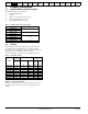
Safety Product Mechanical Electrical Information Information Installation Installation Table 12-16 Getting Started Basic Running the SMARTCARD Onboard Advanced Technical UL Diagnostics Optimization parameters Motor Operation PLC Parameters Data Information Cooper Bussmann dc protection (ARMATURE) fusing for 480V size 1 drives (Included in Quantum MP) Model Rating V Fuse type Rating A Catalog number Control Techniques number 3701-7000090 QMP45A4R 90A FWP-90B QMP75A4R 125A FWP-125A 3701-70012
Safety Product Mechanical Electrical Information Information Installation Installation Table 12-20 Getting Started Basic Running the SMARTCARD Onboard Advanced Technical UL Diagnostics Optimization parameters Motor Operation PLC Parameters Data Information Bussmann semiconductor (line) fusing for 480V size 2 drives (Included in Quantum MP) Four quadrant (R) drIves cannot use Bussmann FWH type fuses for line fusing. See ferraz shawmut Table 12-18 .
Safety Product Mechanical Electrical Information Information Installation Installation Table 12-30 Basic Running the SMARTCARD Onboard Advanced Technical UL Diagnostics Optimization parameters Motor Operation PLC Parameters Data Information Suppression Resistor (SR+ and SR-) terminals Model Connection type All Getting Started Slotted lug Wire gauge Torque setting Nm lb in 14-10 AWG 4 2.92 8 AWG 4.5 3.33 6-4 AWG 5 3.75 2 AWG 5.6 4.
Safety Product Mechanical Electrical Information Information Installation Installation 12.3 Getting Started Basic Running the SMARTCARD Onboard Advanced Technical UL Diagnostics Optimization parameters Motor Operation PLC Parameters Data Information Optional external EMC filters EMC filters can be sourced directly from Schaffner and Epcos. See Table 12-33 for details. It is essential that line rectors be connected between the filter terminals and the power input terminals.
Safety Product Mechanical Electrical Information Information Installation Installation 12.3.
Safety Product Mechanical Electrical Information Information Installation Installation Permissible output current (A) Figure 12-4 Getting Started Basic Running the SMARTCARD Onboard Advanced Technical UL Diagnostics Optimization parameters Motor Operation PLC Parameters Data Information Quantum MP size 2A derating for extended ambient operation 560 550 540 530 520 510 500 490 480 470 460 450 440 430 420 410 400 390 380 370 360 350 340 330 320 310 300 QMP550A4(R) QMP400A4(R) (No derating necessary) Q
Safety Product Mechanical Electrical Information Information Installation Installation 13 Getting Started Basic parameters Running the Motor Optimization Diagnostics SMARTCARD Onboard Advanced Technical UL Diagnostics Operation PLC Parameters Data Information Figure 13-1 Keypad status modes The display on the drive gives various information about the status of the drive.
Safety Product Mechanical Electrical Information Information Installation Installation Getting Started Basic parameters Running the Motor Trip C.cPr 188 C.dAt 183 C.Err 182 C.
Safety Product Mechanical Electrical Information Information Installation Installation Getting Started Basic parameters Running the Motor Trip EnC9 197 EnC10 198 Optimization SMARTCARD Onboard Advanced Technical UL Diagnostics Operation PLC Parameters Data Information Diagnosis Drive encoder trip: Position feedback selected is selected from a Solutions Module slot which does not have a speed / position feedback Solutions Module installed Check setting of Pr 3.26 (Fb01, 0.71) (or Pr 21.
Safety Product Mechanical Electrical Information Information Installation Installation Getting Started Basic parameters Running the Motor Optimization Trip HF11 SMARTCARD Onboard Advanced Technical UL Diagnostics Operation PLC Parameters Data Information Diagnosis Data processing error: Access to EEPROM failed Hardware fault - return drive to supplier HF12 Data processing error: Main program stack overflow Hardware fault - return drive to supplier HF17 Data processing error: No Comms from power p
Safety Product Mechanical Electrical Information Information Installation Installation Getting Started Basic parameters Running the Motor Trip PAd 34 PLL Err Diagnosis Install keypad and reset Change speed reference selector to select speed reference from another source Phase Lock Loop cannot lock to the auxiliary supply Check auxiliary supply is stable PS Internal power supply fault PS.10V 8 PS.24V 9 PSAVE.Er 37 SAVE.
Safety Product Mechanical Electrical Information Information Installation Installation Getting Started Basic parameters Trip S.OV Running the Motor Optimization SMARTCARD Onboard Advanced Technical UL Diagnostics Operation PLC Parameters Data Information Diagnosis Excessive suppressor voltage 172 Operation of the drive requires the installation of the external suppressor resistance, see section 4.10 External suppressor resistor on page 42.
Safety Product Mechanical Electrical Information Information Installation Installation Getting Started Basic parameters Running the Motor Optimization Trip SMARTCARD Onboard Advanced Technical UL Diagnostics Operation PLC Parameters Data Information Diagnosis thS Motor thermistor short circuit 25 Check motor thermistor wiring Replace motor / motor thermistor Set Pr 7.15 (in01, 0.
Safety Product Mechanical Electrical Information Information Installation Installation Table 13-2 Getting Started Basic parameters Running the Motor Optimization SMARTCARD Onboard Advanced Technical UL Diagnostics Operation PLC Parameters Data Information Serial communications look-up table No. String No. String No. String 1 2 3 4 5 6 7 8 9 10 11 12 13 14 15 16 17 18 19 20 21 22 23 24 25 26 27 28 29 30 31 32-33 34 35 36 37 38-39 40-89 UU t002 AOC t004 PS Et O.SPd PS.10V PS.
Safety Product Mechanical Electrical Information Information Installation Installation 13.4 Getting Started Basic parameters Running the Motor Alarm indications Alarm indications Lower display Description Hot Heatsink alarm is active The temperature displayed in Pr 7.04 has exceeded the alarm level (see Pr 7.04). OVLd Motor overload The motor I2t accumulator (Pr 4.
Safety Product Mechanical Electrical Information Information Installation Installation 14 Getting Started Basic Running parameters the Motor UL Information 14.5 Quantum MP frame size 1 drives have been assessed to comply with both ULus and cUL requirements.Control Techniques UL file number is E58592. Confirmation of UL listing can be found at website: www.ul.com Quantum MP frame size 2 drives have been assessed to comply with UL508A open panel requirements. 14.
List of tables Table Table Table Table Table Table Table Table Table Table Table Table Table 2-1 2-2 2-3 2-4 2-5 2-6 2-7 2-8 3-1 3-2 3-3 3-4 3-5 Table 3-6 Table 3-7 Table 3-8 Table Table Table Table 3-9 3-10 4-1 4-2 Table Table Table Table Table Table Table 4-3 4-4 4-5 4-6 4-7 4-8 4-9 Table 4-10 Table 4-11 Table 4-12 Table 4-13 Table 4-14 Table 4-15 Table 4-16 Table 4-17 Table 4-18 Table 4-19 Table Table Table Table Table Table Table Table Table 4-20 4-21 4-22 4-23 4-24 4-25 4-26 5-1 5-2 Model to f
Table 12-23 Cooper Bussmann 120 Vac I/O protection fusing for 480V size 1 drives (Included in Quantum MP) 152 Table 12-24 Quantum MP drive SCR I2t rating for semiconductor fusing 152 Table 12-25 Control terminal data ......................................152 Table 12-26 Auxiliary and Field terminal data ....................152 Table 12-27 Drive power (L1, L2, L3, and GND) terminals 152 Table 12-28 Drive power (A1 and A2) terminals ................
Index Symbols H +10V user output .....................................................................50 +24V external input .................................................................50 +24V user output .....................................................................52 Humidity ................................................................................ 147 I Numerics IP Rating (Ingress protection) ............................................... 148 Items supplied with the drive ......
S Safety Information .....................................................................5 Second motor parameters ....................................................141 Sequencer .............................................................................112 Serial comms lead ..................................................................45 Serial communications port isolation ......................................45 Solutions Module ID codes ...................................................