
User guide


Table Of Contents
- 1 Safety Information
- 2 Product Information
- 3 Mechanical Installation
- 4 Electrical Installation
- 4.1 Electrical connections/ Power connections
- 4.2 Ground connections
- 4.3 AC supply requirements
- 4.4 Line reactors
- 4.5 Auxiliary AC supply and connections
- 4.6 Separating the Auxiliary Supply
- 4.7 Control 120 Vac supply
- 4.8 Control 24 Vdc supply
- 4.9 Cable and fuse size ratings
- 4.10 External suppressor resistor
- 4.11 Ground leakage
- 4.12 EMC (Electromagnetic compatibility)
- 4.13 Serial communications connections
- 4.14 Shield connections
- 4.15 Control connections
- 4.16 General
- 4.17 Connecting an encoder
- 5 Getting Started
- 5.1 Understanding the display
- 5.2 Keypad operation
- 5.3 Menu 0 (sub block)
- 5.4 Pre-defined sub blocks
- 5.5 Menu 0 (linear)
- 5.6 Menu structure
- 5.7 Advanced menus
- 5.8 Saving parameters
- 5.9 Restoring parameter defaults
- 5.10 Displaying parameters with non- default values only
- 5.11 Displaying destination parameters only
- 5.12 Parameter access level and security
- 5.13 Serial communications
- 6 Basic parameters
- 7 Running the Motor
- 8 Optimization
- 9 SMARTCARD Operation
- 9.1 Introduction
- 9.2 Easy saving and reading
- 9.3 Transferring data
- 9.3.1 Writing to the SMARTCARD
- 9.3.2 Reading from the SMARTCARD
- 9.3.3 Auto saving parameter changes
- 9.3.4 Booting up from the SMARTCARD on every power up (Pr 11.42 (SE09, 0.30) = boot (4))
- 9.3.5 Booting up from the SMARTCARD on every power up (Pr xx.00 = 2001)
- 9.3.6 Comparing drive full parameter set with the SMARTCARD values
- 9.3.7 7yyy / 9999 - Erasing data from the SMARTCARD
- 9.3.8 9666 / 9555 - Set / clear SMARTCARD warning suppression flag
- 9.3.9 9888 / 9777 - Set / clear the SMARTCARD read only flag
- 9.4 Data block header information
- 9.5 SMARTCARD parameters
- 9.6 SMARTCARD trips
- 10 Onboard PLC
- 11 Advanced Parameters
- 11.1 Menu 1: Speed reference
- 11.2 Menu 2: Ramps
- 11.3 Menu 3: Speed feedback and speed control
- 11.4 Menu 4: Torque and current control
- 11.5 Menu 5: Motor and field control
- 11.6 Menu 6: Sequencer and clock
- 11.7 Menu 7: Analog I/O
- 11.8 Menu 8: Digital I/O
- 11.9 Menu 9: Programmable logic, motorized pot and binary sum
- 11.10 Menu 10: Status and trips
- 11.11 Menu 11: General drive set-up
- 11.12 Menu 12: Threshold detectors, variable selectors and brake control function
- 11.13 Menu 13: Position control
- 11.14 Menu 14: User PID controller
- 11.15 Menus 15, 16 and 17: Solutions Module slots
- 11.16 SM-I/O120V Solutions Module parameter settings
- 11.17 Menu 18: Application menu 1
- 11.18 Menu 19: Application menu 2
- 11.19 Menu 20: Application menu 3
- 11.20 Menu 21: Second motor parameters
- 11.21 Menu 22: Additional Menu 0 set-up
- 11.22 Menu 23: Header selections
- 11.23 Advanced features
- 12 Technical Data
- 12.1 Drive technical data
- 12.1.1 Power and current ratings
- 12.1.2 Power dissipation
- 12.1.3 AC Supply requirements
- 12.1.4 Supply types
- 12.1.5 SCR bridge AC Supply
- 12.1.6 Auxiliary AC supply
- 12.1.7 Line reactors
- 12.1.8 Temperature, humidity and cooling method
- 12.1.9 Storage
- 12.1.10 Altitude
- 12.1.11 IP Rating
- 12.1.12 Corrosive gasses
- 12.1.13 RoHS compliance
- 12.1.14 Vibration
- 12.1.15 Start up time
- 12.1.16 Output speed range
- 12.1.17 Accuracy
- 12.1.18 Acoustic noise
- 12.1.19 Overall dimensions
- 12.1.20 Weights
- 12.2 Cable and fuse size ratings
- 12.3 Optional external EMC filters
- 12.1 Drive technical data
- 13 Diagnostics
- 14 UL Information
- List of tables
- Index
Safety
Information
Product
Information
Mechanical
Installation
Electrical
Installation
Getting
Started
Basic
parameters
Running the
Motor
Optimization
SMARTCARD
Operation
Onboard
PLC
Advanced
Parameters
Technical
Data
Diagnostics
UL
Information
Quantum MP User Guide 127
Issue: A3 www.emersonct.com
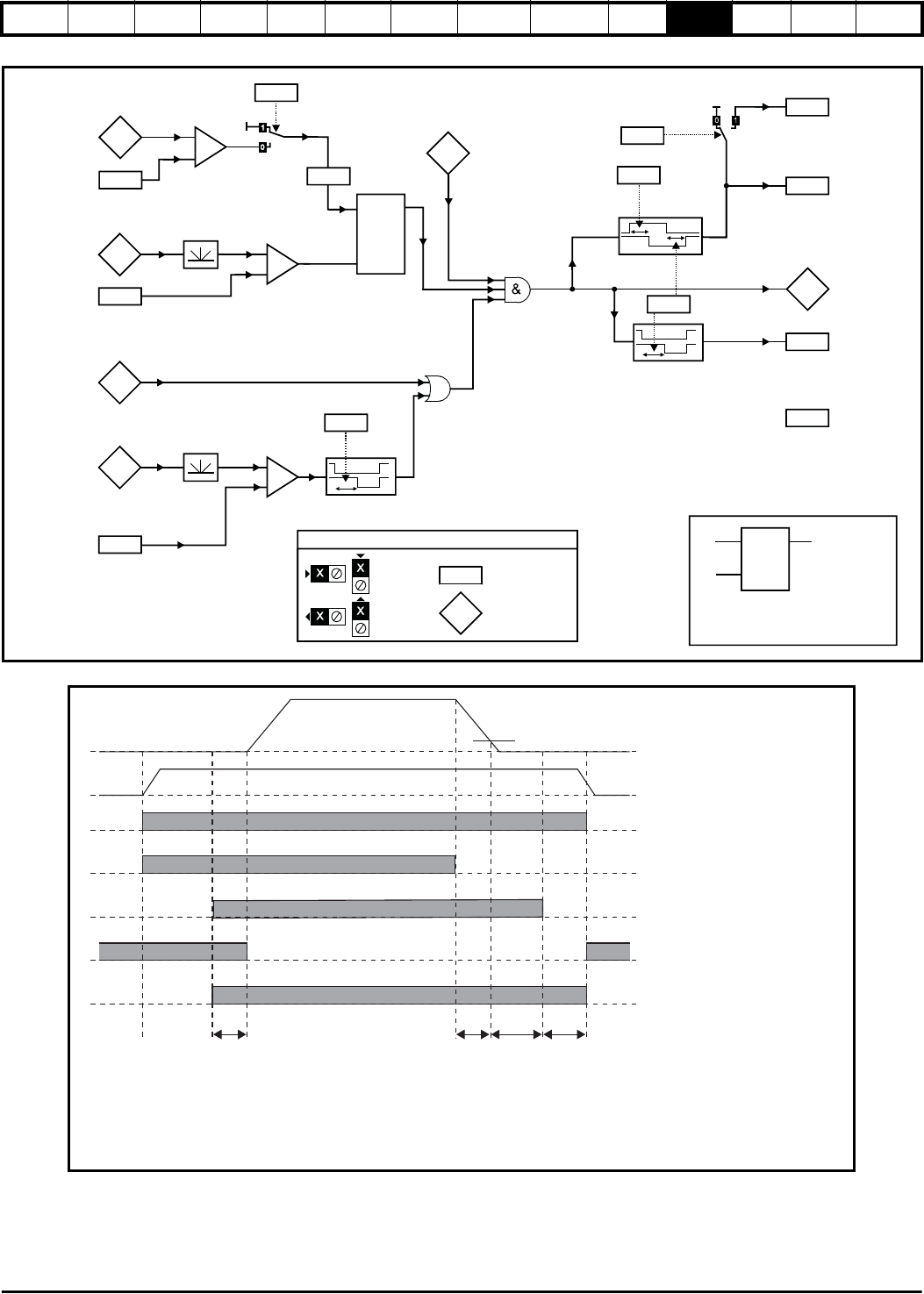
Figure 11-16 Menu 12 Brake control function
Figure 11-17 Brake sequence
Current
magnitude
3.02
Speed
feedback
Brake apply
speed
12.45
+
_
0.XX
0.XX
Key
Read-write (RW)
parameter
Read-only (RO)
parameter
Input
terminals
Output
terminals
LAT
input
reset
output
If the reset input is 1, the output is 0.
If the reset input is 0, the output latches
at 1 if the input is 1.
i
r
o
80% x Rated
field current
1.11
Reference
on
LAT
i
o
r
OR
Brake apply
speed delay
12.46
10.02
Drive active
Post-brake
release delay
12.47
12.40
Brake
release
2.03
6.08
Hold zero
speed
Ramp
hold
12.48
Brake apply
delay
Enable position
controller during
brake release
12.49
13.10
Position
control
mode
( = 1)
5.54
Flux feedback
4.01
Lower current
threshold
12.43
+
_
5.70
+
_
12.41
Brake control
enable
12.50
Field
active
External
field control
12.51
Torque present
1
2
3
4
5
Pr 3.02 Motor Speed
Torque present
Pr 10.02 Drive active
Pr 1.11 Reference on
Pr 12.40 Brake release
Pr 2.03 Ramp hold
PR 13.10 Position control mode
Pr 6.08 Hold zero speed
Pr 12.46Pr12.47 Pr 12.48
Pr 12.45 Speed threshold
1 Wait for armature current and fully fluxed machine
2. Post-brake release delay
3. Wait for speed threshold
4. Wait for brake apply speed delay
5. Brake apply delay