
User guide
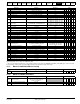
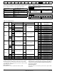


Table Of Contents
- 1 Safety Information
- 2 Product Information
- 3 Mechanical Installation
- 4 Electrical Installation
- 4.1 Electrical connections/ Power connections
- 4.2 Ground connections
- 4.3 AC supply requirements
- 4.4 Line reactors
- 4.5 Auxiliary AC supply and connections
- 4.6 Separating the Auxiliary Supply
- 4.7 Control 120 Vac supply
- 4.8 Control 24 Vdc supply
- 4.9 Cable and fuse size ratings
- 4.10 External suppressor resistor
- 4.11 Ground leakage
- 4.12 EMC (Electromagnetic compatibility)
- 4.13 Serial communications connections
- 4.14 Shield connections
- 4.15 Control connections
- 4.16 General
- 4.17 Connecting an encoder
- 5 Getting Started
- 5.1 Understanding the display
- 5.2 Keypad operation
- 5.3 Menu 0 (sub block)
- 5.4 Pre-defined sub blocks
- 5.5 Menu 0 (linear)
- 5.6 Menu structure
- 5.7 Advanced menus
- 5.8 Saving parameters
- 5.9 Restoring parameter defaults
- 5.10 Displaying parameters with non- default values only
- 5.11 Displaying destination parameters only
- 5.12 Parameter access level and security
- 5.13 Serial communications
- 6 Basic parameters
- 7 Running the Motor
- 8 Optimization
- 9 SMARTCARD Operation
- 9.1 Introduction
- 9.2 Easy saving and reading
- 9.3 Transferring data
- 9.3.1 Writing to the SMARTCARD
- 9.3.2 Reading from the SMARTCARD
- 9.3.3 Auto saving parameter changes
- 9.3.4 Booting up from the SMARTCARD on every power up (Pr 11.42 (SE09, 0.30) = boot (4))
- 9.3.5 Booting up from the SMARTCARD on every power up (Pr xx.00 = 2001)
- 9.3.6 Comparing drive full parameter set with the SMARTCARD values
- 9.3.7 7yyy / 9999 - Erasing data from the SMARTCARD
- 9.3.8 9666 / 9555 - Set / clear SMARTCARD warning suppression flag
- 9.3.9 9888 / 9777 - Set / clear the SMARTCARD read only flag
- 9.4 Data block header information
- 9.5 SMARTCARD parameters
- 9.6 SMARTCARD trips
- 10 Onboard PLC
- 11 Advanced Parameters
- 11.1 Menu 1: Speed reference
- 11.2 Menu 2: Ramps
- 11.3 Menu 3: Speed feedback and speed control
- 11.4 Menu 4: Torque and current control
- 11.5 Menu 5: Motor and field control
- 11.6 Menu 6: Sequencer and clock
- 11.7 Menu 7: Analog I/O
- 11.8 Menu 8: Digital I/O
- 11.9 Menu 9: Programmable logic, motorized pot and binary sum
- 11.10 Menu 10: Status and trips
- 11.11 Menu 11: General drive set-up
- 11.12 Menu 12: Threshold detectors, variable selectors and brake control function
- 11.13 Menu 13: Position control
- 11.14 Menu 14: User PID controller
- 11.15 Menus 15, 16 and 17: Solutions Module slots
- 11.16 SM-I/O120V Solutions Module parameter settings
- 11.17 Menu 18: Application menu 1
- 11.18 Menu 19: Application menu 2
- 11.19 Menu 20: Application menu 3
- 11.20 Menu 21: Second motor parameters
- 11.21 Menu 22: Additional Menu 0 set-up
- 11.22 Menu 23: Header selections
- 11.23 Advanced features
- 12 Technical Data
- 12.1 Drive technical data
- 12.1.1 Power and current ratings
- 12.1.2 Power dissipation
- 12.1.3 AC Supply requirements
- 12.1.4 Supply types
- 12.1.5 SCR bridge AC Supply
- 12.1.6 Auxiliary AC supply
- 12.1.7 Line reactors
- 12.1.8 Temperature, humidity and cooling method
- 12.1.9 Storage
- 12.1.10 Altitude
- 12.1.11 IP Rating
- 12.1.12 Corrosive gasses
- 12.1.13 RoHS compliance
- 12.1.14 Vibration
- 12.1.15 Start up time
- 12.1.16 Output speed range
- 12.1.17 Accuracy
- 12.1.18 Acoustic noise
- 12.1.19 Overall dimensions
- 12.1.20 Weights
- 12.2 Cable and fuse size ratings
- 12.3 Optional external EMC filters
- 12.1 Drive technical data
- 13 Diagnostics
- 14 UL Information
- List of tables
- Index
Safety
Information
Product
Information
Mechanical
Installation
Electrical
Installation
Getting
Started
Basic
parameters
Running the
Motor
Optimization
SMARTCARD
Operation
Onboard
PLC
Advanced
Parameters
Technical
Data
Diagnostics
UL
Information
Quantum MP User Guide 143
Issue: A3 www.emersonct.com
11.23.2 S ramps
Setting this parameter enables the S ramp function.
This parameter defines the maximum rate of change of acceleration/
deceleration. If the S ramp is disabled (Pr 2.06 = 0) a linear ramp is used
and the time in seconds taken for the ramp output to change by speed (Δ
w*) is given by:
Speed
T
Ramp =
Δwω* x A / See Pr 2.39
Where A is the selected ramp rate in s / See Pr 2.39
If the S ramp is enabled (Pr 2.06 = 1) then the ramp time is extended as
shown in the diagram below.
The time taken in seconds for the ramp output to change by speed (Δw*)
is given below. Two cases are given because the total ramp time must
be calculated with a different equation depending on whether the
acceleration is able to reach the selected ramp rate (A1) or not. If the
required change is small the selected ramp rate is not reached and the
ramp does not include the central linear ramp region. If the required
change is larger the ramp does include the central linear region as
shown in the diagram above.
Speed
Δω*
linear
= 1000 x J / A1
2
where:
A = selected ramp rate
J = Pr 2.07
If the required change is less than Δω*
linear
then T
Ramp1
should be used,
but if the speed change is greater or equal to Δs*
linear
T
Ramp2
should be
used.
T
Ramp1
= 2 √ (Δω* x Pr 2.07 / 1000)
T
Ramp2
= (Δω* x A / 1000) + (Pr 2.07 / A)
The default values for the ramp rate and S ramp acceleration limit have
been chosen such that for the default maximum speed, the curved parts
of the S ramp are 25% of the original ramp if S ramp is enabled.
Therefore the ramp time is increased by a factor of 1.5.
11.23.3 Torque modes
The value of this parameter refers to switches TM0 to TM3 on Menu 4
diagram.
When this parameter is set to 1, 2 or 3 the ramps are not active while
the drive is in the run state. When the drive is taken out of the run state,
but not disabled, the appropriate stopping mode is used. It is
recommended that coast stopping or stopping without ramps are used.
However, if ramp stop mode is used the ramp output is pre-loaded with
the actual speed at the changeover point to avoid unwanted jumps in the
speed reference.
0: Speed control mode
The torque demand is equal to the speed loop output.
1: Torque control
The torque demand is given by the sum of the torque reference and
the torque offset, if enabled. The speed is not limited in any way,
however, the drive will trip at the overspeed threshold if runaway
occurs.
2: Torque control with speed override
The output of the speed loop defines the torque demand, but is
limited between 0 and the resultant torque reference (Pr 4.08 +
Pr
4.09 (if enabled)). The effect is to produce an operating area as
shown below if the final speed demand and the resultant torque
reference are both positive. The speed controller will try and
accelerate the machine to the final speed demand level with a
torque demand defined by the resultant torque reference. However,
the speed cannot exceed the reference because the required torque
would be negative, and so it would be clamped to zero.
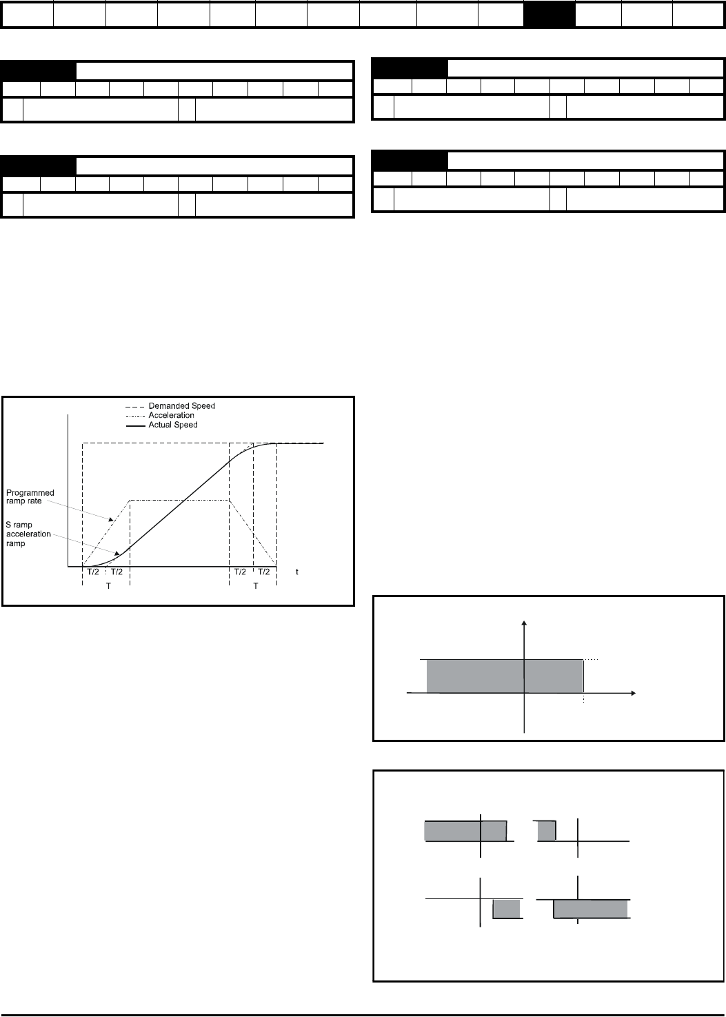
Depending on the sign of the final speed demand and the resultant
torque the four areas of operation shown below are possible.
This mode of operation can be used where torque control is required, but
2.06 S ramp enable
RW Bit US
OFF (0) or On (1)
EUR: OFF (0), USA: On (1)
2.07 S ramp acceleration limit
RW Bit US
0.000 to 100.000 s
2
/1,000rpm
3.600
4.08 Torque reference
RW Bi US
±USER_CURRENT_MAX %
0.00
4.11 Torque mode selector
RW Uni US
0 to 4
0
Pr +
4.08
Pr (if enabled)
4.09
Pr
3.01
Speed
Current
+ final speed demand
+ resultant torque
- final speed demand
+ resultant torque
+ final speed demand
-resultant torque
- final speed demand
- resultant torque