
User guide

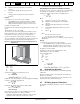


Table Of Contents
- 1 Safety Information
- 2 Product Information
- 3 Mechanical Installation
- 4 Electrical Installation
- 4.1 Electrical connections/ Power connections
- 4.2 Ground connections
- 4.3 AC supply requirements
- 4.4 Line reactors
- 4.5 Auxiliary AC supply and connections
- 4.6 Separating the Auxiliary Supply
- 4.7 Control 120 Vac supply
- 4.8 Control 24 Vdc supply
- 4.9 Cable and fuse size ratings
- 4.10 External suppressor resistor
- 4.11 Ground leakage
- 4.12 EMC (Electromagnetic compatibility)
- 4.13 Serial communications connections
- 4.14 Shield connections
- 4.15 Control connections
- 4.16 General
- 4.17 Connecting an encoder
- 5 Getting Started
- 5.1 Understanding the display
- 5.2 Keypad operation
- 5.3 Menu 0 (sub block)
- 5.4 Pre-defined sub blocks
- 5.5 Menu 0 (linear)
- 5.6 Menu structure
- 5.7 Advanced menus
- 5.8 Saving parameters
- 5.9 Restoring parameter defaults
- 5.10 Displaying parameters with non- default values only
- 5.11 Displaying destination parameters only
- 5.12 Parameter access level and security
- 5.13 Serial communications
- 6 Basic parameters
- 7 Running the Motor
- 8 Optimization
- 9 SMARTCARD Operation
- 9.1 Introduction
- 9.2 Easy saving and reading
- 9.3 Transferring data
- 9.3.1 Writing to the SMARTCARD
- 9.3.2 Reading from the SMARTCARD
- 9.3.3 Auto saving parameter changes
- 9.3.4 Booting up from the SMARTCARD on every power up (Pr 11.42 (SE09, 0.30) = boot (4))
- 9.3.5 Booting up from the SMARTCARD on every power up (Pr xx.00 = 2001)
- 9.3.6 Comparing drive full parameter set with the SMARTCARD values
- 9.3.7 7yyy / 9999 - Erasing data from the SMARTCARD
- 9.3.8 9666 / 9555 - Set / clear SMARTCARD warning suppression flag
- 9.3.9 9888 / 9777 - Set / clear the SMARTCARD read only flag
- 9.4 Data block header information
- 9.5 SMARTCARD parameters
- 9.6 SMARTCARD trips
- 10 Onboard PLC
- 11 Advanced Parameters
- 11.1 Menu 1: Speed reference
- 11.2 Menu 2: Ramps
- 11.3 Menu 3: Speed feedback and speed control
- 11.4 Menu 4: Torque and current control
- 11.5 Menu 5: Motor and field control
- 11.6 Menu 6: Sequencer and clock
- 11.7 Menu 7: Analog I/O
- 11.8 Menu 8: Digital I/O
- 11.9 Menu 9: Programmable logic, motorized pot and binary sum
- 11.10 Menu 10: Status and trips
- 11.11 Menu 11: General drive set-up
- 11.12 Menu 12: Threshold detectors, variable selectors and brake control function
- 11.13 Menu 13: Position control
- 11.14 Menu 14: User PID controller
- 11.15 Menus 15, 16 and 17: Solutions Module slots
- 11.16 SM-I/O120V Solutions Module parameter settings
- 11.17 Menu 18: Application menu 1
- 11.18 Menu 19: Application menu 2
- 11.19 Menu 20: Application menu 3
- 11.20 Menu 21: Second motor parameters
- 11.21 Menu 22: Additional Menu 0 set-up
- 11.22 Menu 23: Header selections
- 11.23 Advanced features
- 12 Technical Data
- 12.1 Drive technical data
- 12.1.1 Power and current ratings
- 12.1.2 Power dissipation
- 12.1.3 AC Supply requirements
- 12.1.4 Supply types
- 12.1.5 SCR bridge AC Supply
- 12.1.6 Auxiliary AC supply
- 12.1.7 Line reactors
- 12.1.8 Temperature, humidity and cooling method
- 12.1.9 Storage
- 12.1.10 Altitude
- 12.1.11 IP Rating
- 12.1.12 Corrosive gasses
- 12.1.13 RoHS compliance
- 12.1.14 Vibration
- 12.1.15 Start up time
- 12.1.16 Output speed range
- 12.1.17 Accuracy
- 12.1.18 Acoustic noise
- 12.1.19 Overall dimensions
- 12.1.20 Weights
- 12.2 Cable and fuse size ratings
- 12.3 Optional external EMC filters
- 12.1 Drive technical data
- 13 Diagnostics
- 14 UL Information
- List of tables
- Index

Safety
Information
Product
Information
Mechanical
Installation
Electrical
Installation
Getting
Started
Basic
parameters
Running the
Motor
Optimization
SMARTCARD
Operation
Onboard
PLC
Advanced
Parameters
Technical
Data
Diagnostics
UL
Information
22 Quantum MP User Guide
www.emersonct.com Issue: A3
enclosure
T
int
Maximum permissible temperature in
o
C inside the
enclosure
P Power in Watts dissipated by all heat sources in the
enclosure
k Heat transmission coefficient of the enclosure material
in W/m
2
/
o
C
Example
To calculate the size of an enclosure for the following:
• Two QMP25A4 models operating under full load conditions
• Maximum ambient temperature inside the enclosure: 40°C
• Maximum ambient temperature outside the enclosure: 30°C
Dissipation of each drive: 125W
Dissipation from other heat generating equipment in the enclosure. 11W
(max).
Total dissipation: 2 x (125 + 11) = 272W
The enclosure is to be made from painted 2mm (0.079in) sheet steel
having a heat transmission coefficient of 5.5 W/m
2
/
o
C. Only the top,
front, and two sides of the enclosure are free to dissipate heat.
The value of 5.5 W/m
2
/ºC can generally be used with a sheet steel
enclosure (exact values can be obtained by the supplier of the material).
If in any doubt, allow for a greater margin in the temperature rise.
Figure 3-10 Enclosure having front, sides and top panels free to
dissipate heat
Insert the following values:
T
int
40°C
T
ext
30°C
k 5.5
P 272W
The minimum required heat conducting area is then:
= 4.945 m
2
(53.90 ft
2
) (1 m
2
= 10.9 ft
2
)
Estimate two of the enclosure dimensions - the height (H) and depth (D),
for instance. Calculate the width (W) from:
Inserting H = 2m and D = 0.6m, obtain the minimum width:
=0.979 m (38.5 in)
If the enclosure is too large for the space available, it can be made
smaller only by attending to one or all of the following:
• Reducing the ambient temperature outside the enclosure, and/or
applying forced-air cooling to the outside of the enclosure
• Reducing the number of drives in the enclosure
• Removing other heat-generating equipment
Calculating the air-flow in a ventilated enclosure
The dimensions of the enclosure are required only for accommodating
the equipment. The equipment is cooled by the forced air flow.
Calculate the minimum required volume of ventilating air from:
Where:
V Air-flow in m
3
per hour (1 m
3
/hr = 0.59 ft
3
/min)
T
ext
Maximum expected temperature in
°C outside the
enclosure
T
int
Maximum permissible temperature in °C inside the
enclosure
P Power in Watts dissipated by all heat sources in the
enclosure
k Ratio of
Where:
P
0
is the air pressure at sea level
P
I
is the air pressure at the installation
Typically use a factor of 1.2 to 1.3, to allow also for pressure-drops in
dirty air-filters.
Example
To calculate the size of an enclosure for the following:
• Three QMP45A4 models operating under full load conditions
• Maximum ambient temperature inside the enclosure: 40°C
• Maximum ambient temperature outside the enclosure: 30°C
Dissipation of each drive: 168W
Dissipation from other heat generating equipment. 15 W
Total dissipation: 3 x (168 + 15) = 549W
Insert the following values:
T
int
40°C
T
ext
30°C
k 1.3
P 549W
Then:
= 214.1 m
3
/hr (126.3 ft
3
/min) (1 m
3
/ hr = 0.59 ft
3
/min)
3.6 Heatsink fan operation
Quantum MP drive rated 75A and above are ventilated by internally
supplied fans.
Ensure the minimum clearances around the drive are maintained to
allow the air to flow freely.
The drive controls the fan operation based on the temperature of the
heatsink and the drives thermal model system.
3.7 IP Rating (Ingress Protection)
An explanation of IP Rating is provided in section 12.1.11 IP Rating on
page 148.
W
H
D
A
e
272W
5.5 40 30–()
---------------------------------
=
W
A
e
2HD–
HD+
--------------------------
=
W
4.945 2 2× 0.6×()–
20.6+
-----------------------------------------------------
=
V
3kP
T
int
T
ext
–
---------------------------
=
P
o
P
l
-------
V
31.3× 549×
40 30–
----------------------------------
=