
User guide


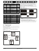

Table Of Contents
- 1 Safety Information
- 2 Product Information
- 3 Mechanical Installation
- 4 Electrical Installation
- 4.1 Electrical connections/ Power connections
- 4.2 Ground connections
- 4.3 AC supply requirements
- 4.4 Line reactors
- 4.5 Auxiliary AC supply and connections
- 4.6 Separating the Auxiliary Supply
- 4.7 Control 120 Vac supply
- 4.8 Control 24 Vdc supply
- 4.9 Cable and fuse size ratings
- 4.10 External suppressor resistor
- 4.11 Ground leakage
- 4.12 EMC (Electromagnetic compatibility)
- 4.13 Serial communications connections
- 4.14 Shield connections
- 4.15 Control connections
- 4.16 General
- 4.17 Connecting an encoder
- 5 Getting Started
- 5.1 Understanding the display
- 5.2 Keypad operation
- 5.3 Menu 0 (sub block)
- 5.4 Pre-defined sub blocks
- 5.5 Menu 0 (linear)
- 5.6 Menu structure
- 5.7 Advanced menus
- 5.8 Saving parameters
- 5.9 Restoring parameter defaults
- 5.10 Displaying parameters with non- default values only
- 5.11 Displaying destination parameters only
- 5.12 Parameter access level and security
- 5.13 Serial communications
- 6 Basic parameters
- 7 Running the Motor
- 8 Optimization
- 9 SMARTCARD Operation
- 9.1 Introduction
- 9.2 Easy saving and reading
- 9.3 Transferring data
- 9.3.1 Writing to the SMARTCARD
- 9.3.2 Reading from the SMARTCARD
- 9.3.3 Auto saving parameter changes
- 9.3.4 Booting up from the SMARTCARD on every power up (Pr 11.42 (SE09, 0.30) = boot (4))
- 9.3.5 Booting up from the SMARTCARD on every power up (Pr xx.00 = 2001)
- 9.3.6 Comparing drive full parameter set with the SMARTCARD values
- 9.3.7 7yyy / 9999 - Erasing data from the SMARTCARD
- 9.3.8 9666 / 9555 - Set / clear SMARTCARD warning suppression flag
- 9.3.9 9888 / 9777 - Set / clear the SMARTCARD read only flag
- 9.4 Data block header information
- 9.5 SMARTCARD parameters
- 9.6 SMARTCARD trips
- 10 Onboard PLC
- 11 Advanced Parameters
- 11.1 Menu 1: Speed reference
- 11.2 Menu 2: Ramps
- 11.3 Menu 3: Speed feedback and speed control
- 11.4 Menu 4: Torque and current control
- 11.5 Menu 5: Motor and field control
- 11.6 Menu 6: Sequencer and clock
- 11.7 Menu 7: Analog I/O
- 11.8 Menu 8: Digital I/O
- 11.9 Menu 9: Programmable logic, motorized pot and binary sum
- 11.10 Menu 10: Status and trips
- 11.11 Menu 11: General drive set-up
- 11.12 Menu 12: Threshold detectors, variable selectors and brake control function
- 11.13 Menu 13: Position control
- 11.14 Menu 14: User PID controller
- 11.15 Menus 15, 16 and 17: Solutions Module slots
- 11.16 SM-I/O120V Solutions Module parameter settings
- 11.17 Menu 18: Application menu 1
- 11.18 Menu 19: Application menu 2
- 11.19 Menu 20: Application menu 3
- 11.20 Menu 21: Second motor parameters
- 11.21 Menu 22: Additional Menu 0 set-up
- 11.22 Menu 23: Header selections
- 11.23 Advanced features
- 12 Technical Data
- 12.1 Drive technical data
- 12.1.1 Power and current ratings
- 12.1.2 Power dissipation
- 12.1.3 AC Supply requirements
- 12.1.4 Supply types
- 12.1.5 SCR bridge AC Supply
- 12.1.6 Auxiliary AC supply
- 12.1.7 Line reactors
- 12.1.8 Temperature, humidity and cooling method
- 12.1.9 Storage
- 12.1.10 Altitude
- 12.1.11 IP Rating
- 12.1.12 Corrosive gasses
- 12.1.13 RoHS compliance
- 12.1.14 Vibration
- 12.1.15 Start up time
- 12.1.16 Output speed range
- 12.1.17 Accuracy
- 12.1.18 Acoustic noise
- 12.1.19 Overall dimensions
- 12.1.20 Weights
- 12.2 Cable and fuse size ratings
- 12.3 Optional external EMC filters
- 12.1 Drive technical data
- 13 Diagnostics
- 14 UL Information
- List of tables
- Index

Safety
Information
Product
Information
Mechanical
Installation
Electrical
Installation
Getting
Started
Basic
parameters
Running the
Motor
Optimization
SMARTCARD
Operation
Onboard
PLC
Advanced
Parameters
Technical
Data
Diagnostics
UL
Information
52 Quantum MP User Guide
www.emersonct.com Issue: A3
21 0V common
Function
Common connection for all external
devices
22 +24V user output
Function Supply for external digital devices
Nominal output current 200 mA (including all digital I/O)
Maximum output current 240 mA (including all digital I/O)
Protection Current limit and trip
23 0V common
Function
Common connection for all external
devices
24 Digital I/O 1
25 Digital I/O 2
26 Digital I/O 3
Terminal 24 default function AT SPEED output
Terminal 25 default function Not programmed
Terminal 26 default function Not programmed
Type
Positive or negative logic digital inputs,
positive or negative logic push-pull outputs
or open collector outputs
Input / output mode controlled by... Pr 8.31, Pr 8.32 and Pr 8.33
Operating as an input
Logic mode controlled by... Pr 8.29
Absolute maximum applied voltage
range
+30V, -18V relative to 0V
Impedance
6k
Ω
Input thresholds 10.0V ±0.8V
Operating as an output
Open collector outputs selected Pr 8.30
Nominal maximum output current 200 mA (total including terminal 22)
Maximum output current 240 mA (total including terminal 22)
Common to all modes
Voltage range 0V to +24V
Sampling period
250
μs if configured with the destination as
Pr 6.35 or Pr 6.36. 4 ms for all other
destinations
27 Digital input 1
28 Digital input 2
29 Digital input 3
Terminal 27 default function Not programmed
Terminal 28 default function LOCAL/REMOTE select
Terminal 29 default function Not programmed
Type of input Negative or positive logic digital inputs
Logic mode controlled by... Pr 8.29
Voltage range 0V to +24V
Absolute maximum applied voltage
range
+30V, -18V relative to 0V
Impedance
6k
Ω
Input thresholds 10.0V ±0.8V
Sampling period
250
μs if configured with the destination as
Pr 6.35 or Pr 6.36. 4 ms for all other
destinations
30 0V common
Function
Common connection for all external
devices
31 ENABLE
Function Drive enable
Type Positive or negative logic digital input
Absolute maximum applied voltage
range
+30V, -18V relative to 0V
Input threshold 10.0V ±0.8V
Sampling period 4 ms
Drive commissioning output
Function
Instantaneous armature current
feedback
Type of output Unipolar single-ended voltage
Full scale voltage range 10V ±5%
Full scale range 2.3 X Drive Rated Current [Pr 11.32]
Maximum offset 7 mV
Protection
~25 mA max. Short circuit protection to
ground (0V).
Model Full scale range of drive commissioning output
QMP45A4(R)
2.30 x Drive rated current
(PR 11.32)
QMP75A4(R)
2.42 x Drive rated current
(PR 11.32)
QMP155A4(R)
2.30 x Drive rated current
(PR 11.32)
QMP210A4(R)
2.41 x Drive rated current
(PR 11.32)
41 Tachgenerator positive input
42 Tachgenerator negative input
Function
Speed feedback inputs for
tachgenerator feedback device
Maximum voltage 300V
Feedback scaling controlled by Pr 3.51 (Fb02, 0.72)
Sampling period 4 ms
Status relay contacts are over-voltage category II.
A fuse or other over-current protection should be installed to
the relay circuit.
WARNING
WARNING