
User guide


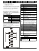
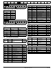
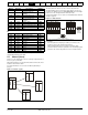

Table Of Contents
- 1 Safety Information
- 2 Product Information
- 3 Mechanical Installation
- 4 Electrical Installation
- 4.1 Electrical connections/ Power connections
- 4.2 Ground connections
- 4.3 AC supply requirements
- 4.4 Line reactors
- 4.5 Auxiliary AC supply and connections
- 4.6 Separating the Auxiliary Supply
- 4.7 Control 120 Vac supply
- 4.8 Control 24 Vdc supply
- 4.9 Cable and fuse size ratings
- 4.10 External suppressor resistor
- 4.11 Ground leakage
- 4.12 EMC (Electromagnetic compatibility)
- 4.13 Serial communications connections
- 4.14 Shield connections
- 4.15 Control connections
- 4.16 General
- 4.17 Connecting an encoder
- 5 Getting Started
- 5.1 Understanding the display
- 5.2 Keypad operation
- 5.3 Menu 0 (sub block)
- 5.4 Pre-defined sub blocks
- 5.5 Menu 0 (linear)
- 5.6 Menu structure
- 5.7 Advanced menus
- 5.8 Saving parameters
- 5.9 Restoring parameter defaults
- 5.10 Displaying parameters with non- default values only
- 5.11 Displaying destination parameters only
- 5.12 Parameter access level and security
- 5.13 Serial communications
- 6 Basic parameters
- 7 Running the Motor
- 8 Optimization
- 9 SMARTCARD Operation
- 9.1 Introduction
- 9.2 Easy saving and reading
- 9.3 Transferring data
- 9.3.1 Writing to the SMARTCARD
- 9.3.2 Reading from the SMARTCARD
- 9.3.3 Auto saving parameter changes
- 9.3.4 Booting up from the SMARTCARD on every power up (Pr 11.42 (SE09, 0.30) = boot (4))
- 9.3.5 Booting up from the SMARTCARD on every power up (Pr xx.00 = 2001)
- 9.3.6 Comparing drive full parameter set with the SMARTCARD values
- 9.3.7 7yyy / 9999 - Erasing data from the SMARTCARD
- 9.3.8 9666 / 9555 - Set / clear SMARTCARD warning suppression flag
- 9.3.9 9888 / 9777 - Set / clear the SMARTCARD read only flag
- 9.4 Data block header information
- 9.5 SMARTCARD parameters
- 9.6 SMARTCARD trips
- 10 Onboard PLC
- 11 Advanced Parameters
- 11.1 Menu 1: Speed reference
- 11.2 Menu 2: Ramps
- 11.3 Menu 3: Speed feedback and speed control
- 11.4 Menu 4: Torque and current control
- 11.5 Menu 5: Motor and field control
- 11.6 Menu 6: Sequencer and clock
- 11.7 Menu 7: Analog I/O
- 11.8 Menu 8: Digital I/O
- 11.9 Menu 9: Programmable logic, motorized pot and binary sum
- 11.10 Menu 10: Status and trips
- 11.11 Menu 11: General drive set-up
- 11.12 Menu 12: Threshold detectors, variable selectors and brake control function
- 11.13 Menu 13: Position control
- 11.14 Menu 14: User PID controller
- 11.15 Menus 15, 16 and 17: Solutions Module slots
- 11.16 SM-I/O120V Solutions Module parameter settings
- 11.17 Menu 18: Application menu 1
- 11.18 Menu 19: Application menu 2
- 11.19 Menu 20: Application menu 3
- 11.20 Menu 21: Second motor parameters
- 11.21 Menu 22: Additional Menu 0 set-up
- 11.22 Menu 23: Header selections
- 11.23 Advanced features
- 12 Technical Data
- 12.1 Drive technical data
- 12.1.1 Power and current ratings
- 12.1.2 Power dissipation
- 12.1.3 AC Supply requirements
- 12.1.4 Supply types
- 12.1.5 SCR bridge AC Supply
- 12.1.6 Auxiliary AC supply
- 12.1.7 Line reactors
- 12.1.8 Temperature, humidity and cooling method
- 12.1.9 Storage
- 12.1.10 Altitude
- 12.1.11 IP Rating
- 12.1.12 Corrosive gasses
- 12.1.13 RoHS compliance
- 12.1.14 Vibration
- 12.1.15 Start up time
- 12.1.16 Output speed range
- 12.1.17 Accuracy
- 12.1.18 Acoustic noise
- 12.1.19 Overall dimensions
- 12.1.20 Weights
- 12.2 Cable and fuse size ratings
- 12.3 Optional external EMC filters
- 12.1 Drive technical data
- 13 Diagnostics
- 14 UL Information
- List of tables
- Index

Safety
Information
Product
Information
Mechanical
Installation
Electrical
Installation
Getting
Started
Basic
parameters
Running the
Motor
Optimization
SMARTCARD
Operation
Onboard
PLC
Advanced
Parameters
Technical
Data
Diagnostics
UL
Information
54 Quantum MP User Guide
www.emersonct.com Issue: A3
4.17 Connecting an encoder
Additional measures to prevent unwanted emission of radio frequency
noise are only required where the installation is subject to specific
requirements for radio frequency emission.
Encoder connections:
To ensure suppression of radio frequency emission, observe the
following:
• Use an encoder with the correct impedance
• Use a cable with individually shielded twisted pairs.
• Connect the cable shields to 0V at both the drive and the encoder,
using the shortest possible links (pig-tails).
• The cable should not be interrupted. If interruptions are unavoidable,
ensure the absolute minimum length of "pig-tail" in the shield
connections at each interruption. Use a connection method that
provides substantial metallic clamps for the cable shield
terminations.
The above applies where the encoder body is isolated from the motor
and where the encoder circuit is isolated from the encoder body. Where
there is no isolation between the encoder circuits and motor body, and in
case of doubt, the following additional requirements must be observed to
give the best possible noise immunity.
• The shields must be directly clamped to the encoder and to the
drives grounding bracket. This may be achieved by clamping of the
individual shields or by providing an additional overall shield that is
clamped.
The recommendations of the encoder manufacturer should also be
adhered to for the encoder connections.
N
In order to guarantee maximum noise immunity for any application
double shielded cable as shown should be used.
In some cases single shielding of each pair of differential signals cables,
or a single overall shield with individual shield on the thermistor
connections is sufficient. In these cases all the shields should be
connected to ground and 0V at both ends.
If the 0V is required to be left floating a cable with individual shields and
an overall shield must be used.
Figure 4-20 and Figure 4-21 illustrate the preferred construction of cable
and the method of clamping. The outer sheath of the cable should be
stripped back enough to allow the clamp to be installed. The shield must
not be broken or opened at this point. The clamps should be installed
close to the drive or feedback device, with the ground connections made
to a ground plate or similar metallic ground surface.
Figure 4-20 Feedback cable, twisted pair
Figure 4-21 Feedback cable connections
Table 4-26 Encoder types
NOTE
NOTE
Pr 3.38
(Fb07, 0.77)
setting
Description
Ab (0)
Quadrature incremental encoder with or without marker
pulse
Fd (1)
Incremental encoder with frequency pulses and
direction, with or without marker pulse
Fr (2)
Incremental encoder with forward pulses and reverse
pulses, with or without marker pulse